DEK INFINITY USER MANUAL.pdf.pdf - 第47页
INFINITY 0$&+,1 (352*5 $00,1* 67$*(& '( ',&$7(' 722/,1* Soft ware Ver sion 7 User Manual 1.45 46. Raise t he printhead using two button control. 47. Fit t he head prop. 48. Pr ess Conf i…
INFINITY
0$&+,1(352*5$00,1*
67$*(&'(',&$7('722/,1*
1.44 User Manual Software Version 7
30.Press the System button.
31.Select Home Camera (F4).
32.Select Print Height (F7).
33.Select Raise Head (F2).
34.Raise the printhead using two button control.
35.Fit the head prop.
36.Press Confirm (F1).
37.Check that the setup of the tooling is adequate for the board, adjust as
necessary.
38.Select Lower Head (F2).
39.Remove the Head Prop.
40.Select Confirm (F1).
41.Lower the printhead using two button control.
42.Close the front printhead cover.
43.Press the System button.
44.Select Home Position (F7).
45.Select Raise Head (F2).
Adjust
Raise
Head
Remove
Cleaner
Home
Camera
Full
Width
Load
Width
Print
Height
Exit
Adjust
Raise
Head
Remove
Cleaner
Board
Stop
Full
Width
Load
Width
Print
Height
Exit
Raise
Head
Home
Position
Exit
Confirm
Lower
Head
Adjust
Lower
Head
Board
Clamps
Set
Stop
Confirm Cancel
Raise
Head
Home
Position
Exit
Adjust
Raise
Head
Remove
Cleaner
Board
Stop
Full
Width
Load
Width
Print
Height
Exit
INFINITY
0$&+,1(352*5$00,1*
67$*(&'(',&$7('722/,1*
Software Version 7 User Manual 1.45
46.Raise the printhead using two button control.
47.Fit the head prop.
48.Press Confirm (F1).
49.Select Board Clamps (F3), to open the clamps.
50.Remove the board from the rails.
51.Select Lower Head (F2).
52.Remove the Head Prop.
53.Select Confirm (F1).
54.Lower the printhead using two button control.
55.Close the front printhead cover.
56.Press the System button.
57.Select Exit (F8).
58.Go to Stage 7.
Confirm
Lower
Head
Adjust
Lower
Head
Board
Clamps
Set
Stop
Adjust
Lower
Head
Board
Clamps
Set
Stop
Confirm Cancel
Adjust
Raise
Head
Remove
Cleaner
Board
Stop
Full
Width
Load
Width
Print
Height
Exit
INFINITY
0$&+,1(352*5$00,1*
67$*('08/7,)/(;722/,1*
1.46 User Manual Software Version 7
STAGE 6D - MULTIFLEX TOOLING
WARNING
BOARD CLAMPS. EXTREME CARE MUST BE EXERCISED WHEN WORKING IN
THE TOOLING AREA OF THE MACHINE TO AVOID INJURY. THE FOILS ON THE
FRONT AND REAR BOARD CLAMPS ARE VERY SHARP.
CAUTION
BOARD CLAMPS. Care must be taken to ensure that the board clamps
are not damaged when removing or replacing tooling.
NOTE
Setting up the MultiFlex tooling is to be performed off the machine.
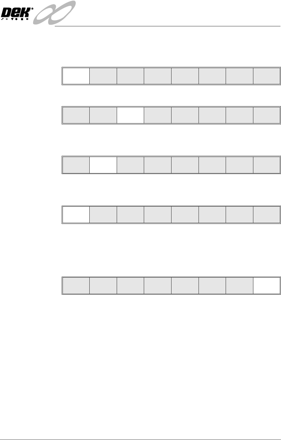
1. Create a box the same size as the board using the side plates.
2. Use the board width and board length dimensions to position the box
correctly.
3. Place the PCB on a flat surface, component side up.
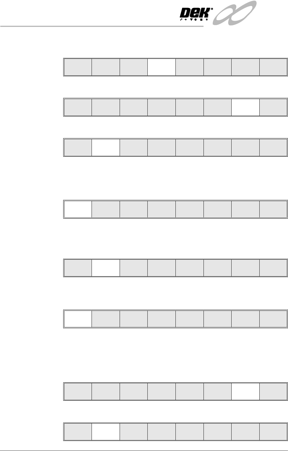
4. Position the acetate template, supplied with the tooling, over the PCB such
that the front edge of the board is aligned with the arrow indicators on the
template. Ensure that the centreline of the board is aligned with the template
zero.
5. Using the grid co-ordinates marked on the template, position pins which
coincide with gaps between the underside board components.