DEK INFINITY USER MANUAL.pdf.pdf - 第85页
INFINITY 0$&+,1 (352*5 $00,1* 67$*( 35,17 ,167(30 2'( Soft ware Ver sion 7 User Manual 1.83 7. Select Step (F1). 8. Select Step (F1) 9. Select Step (F1) 10. Se lect Step (F1) 11 . S e l e c t Auto Board…
INFINITY
0$&+,1(352*5$00,1*
67$*(35,17,167(302'(
1.82 User Manual Software Version 7
Selecting End Run clears the warning window, the print cycle is aborted and
control is returned to the ready page.
If the Unload Board Start in Set Preferences is set to Separation, the follow-
ing window and menu bar is displayed:
Selecting Continue Run clears the warning window and the print cycle
continues.
Selecting End Run clears the warning window, the print cycle is aborted and
control is returned to the ready page.
NOTE
If Camera Idle Position is set to Behind Rail and Unload Board Start is set
to Separation, the warning windows appear one after the other in the order
shown above.
2. Load a board on to the conveyor.
3. Select Auto Board (F1).
4. Select Step (F1).
5. Select Step (F1).
6. Select Step (F1).
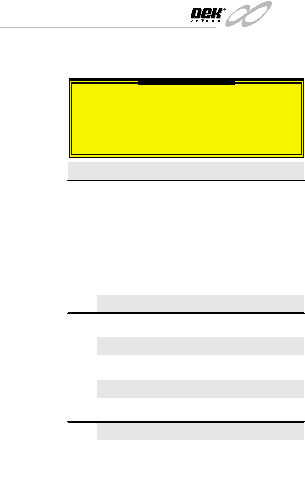
Unload Board Speedup Warning
The UNLOAD BOARD SPEEDUP option is set to
'Separation'
With this option enabled it should be noted
that there is only a minimal clearance
between the underside of the board and any
tooling being used, while the board is being
unloaded.
This option must not be used for boards that
are populated on the underside, as this
could damage the boards.
Continue
Run
End
Run
Auto
Board
Manual
Board
Knead
Paste
Exit
Step Head
Inspect
Setup
Single Exit
Step Head
Inspect
Setup
Single Exit
Step Head
Fiducial
Setup
Adjust
Search
Step
Search
Reset
Single Exit
INFINITY
0$&+,1(352*5$00,1*
67$*(35,17,167(302'(
Software Version 7 User Manual 1.83
7. Select Step (F1).
8. Select Step (F1)
9. Select Step (F1)
10.Select Step (F1)
11. Select Auto Board (F1)
12.Remove the board from the conveyor and inspect the print for alignment. If
the alignment is satisfactory go to Step 16, if the alignment needs adjusting,
calculate the following:
X Offset, Y Offset and θ Offset.
13.Select Edit Data (F3)
14.Enter the X Offset, Y Offset and θ Offset, calculated in Step 12 to both the
Forward and Reverse set of offsets.
15.Repeat Steps 1-12 until the alignment is correct for both a forward and
reverse print.
16.If 2D Inspection is being used continue with Stage 9, if 2D Inspection isn’t
being used go to Stage 10.
Step Head
Fiducial
Setup
Adjust
Search
Step
Search
Reset
Single Exit
Step Head
Fiducial
Setup
Adjust
Search
Step
Search
Reset
Single Exit
Step Head
Fiducial
Setup
Adjust
Search
Step
Search
Reset
Single Exit
Step
Inspect
setup
Single Exit
Auto
Board
Manual
Board
Single Exit
Auto
Adjust
Load
Data
Edit
Data
Setup
Squeegee
Change
Screen
Change
Tooling
Change
Language
Exit

INFINITY
0$&+,1(352*5$00,1*
67$*(',6(783
1.84 User Manual Software Version 7
STAGE 9 - 2DI SETUP
For a complete explanation of 2D inspection and its setup refer to the 2D
Inspection chapter of this manual.