ASM_Guide To Adhesive Dot Dispensing_Stinger_en_0321_online.pdf - 第12页
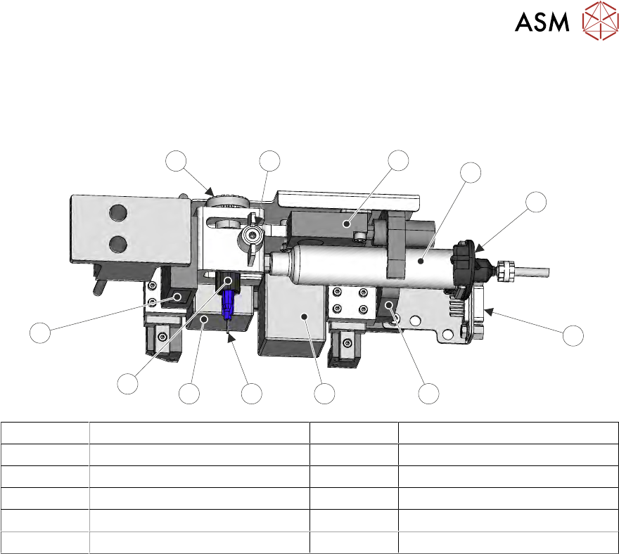
2 STINGER, A GUIDE TO ADHESIVE DOT DISPENSING 2.2 INTRODUCTION 12 GUIDE TO ADHESIVE DOT DISPENSING STINGER 03/2021 1 2 3 4 5 1 Level Sensor 7 Nozzle 2 Syringe 8 Auger Motor 3 Pneumatic Connector 9 Auger 4 Electrical Conn…
2 STINGER, A GUIDE TO ADHESIVE DOT DISPENSING
2.2 INTRODUCTION
GUIDE TO ADHESIVE DOT DISPENSING STINGER 03/2021 11
2.2.1.3 Syringe Assembly
The syringe attaches to an auger assembly at its outlet end and to a pneumatic supply at the other
end; the unit is supported in a ‘C’ shaped clamp. The auger, a ‘T’ shaped valve, is held in the dis-
penser with a plastic clamp screw; it engages with a motor driven pulley.
1
2
5
3
4
67
11
8
9
10
12
1 Level Sensor 7 Nozzle
2 Syringe 8 Auger Motor
3 Pneumatic Connector 9 Auger
4 Electrical Connector 10 Laser
5 ‘C’ Clamp 11 Auger Motor Pulley
6 Z Axis Motor 12 Auger Clamp Screw
A slightly positive air pressure is pulsed at the rear of the syringe to ensure the auger valve is not
starved of adhesive and a consistent supply is maintained. The pulses are programmed in software
to correspond with the auger feed movement phases of the dispense cycle.
2.2.1.4 Adhesive Delivery Mechanism
The delivery mechanism consists of an Archimedes screw fitted in the auger valve. A stepper mo-
tor and pulley assembly (not shown) rotate the screw in the auger valve. This action, combined with
the positive air feed at the rear of the syringe, ensure a consistent level of dispense when used in
the correct operating conditions (temperature/humidity). The auger is purged with adhesive after a
syringe has been replaced.
The drive rotates for a pre-programmed number of steps in the feed direction. The adhesive flows
out of the nozzle onto the product surface, forming a dot. At the end of each dispense, the motor
can be reversed, this allows the auger to draw adhesive back into the nozzle to avoid ‘stringing’.
The number of motor steps, speed, and direction are programmable parameters.
2 STINGER, A GUIDE TO ADHESIVE DOT DISPENSING
2.2 INTRODUCTION
12 GUIDE TO ADHESIVE DOT DISPENSING STINGER 03/2021
1
2
3
4
5
1 Level Sensor 7 Nozzle
2 Syringe 8 Auger Motor
3 Pneumatic Connector 9 Auger
4 Electrical Connector 10 Laser
5 ‘C’ Clamp 11 Auger Motor Pulley
6 Z Axis Motor 12 Auger Clamp Screw
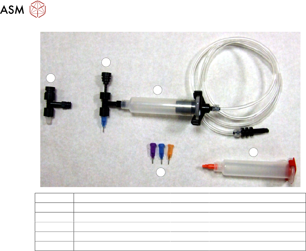
2.2.1.5 Nozzles
At the bottom of the auger valve a nozzle is fitted. Nozzles come in different sizes to suit the pro-
cess. They are identified by body colour: Purple tip i.d.= 0.51mm (inside diameter at the tip), Blue =
0.41mm tip i.d, Orange = 0.33mm tip i.d. and Red = 0.25 tip i.d.
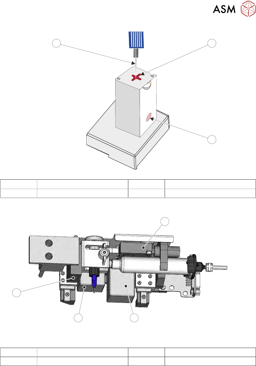
2.2.2 Purge Station
The purge station houses a waste container, which collects the waste purged adhesive. On the lid
of the station is a wiper target; this target allows the syringe nozzle to be wiped after a purge opera-
tion. The purge operation is carried out during product set up/product changeover or, if a nozzle or
a syringe have been replaced during a batch print. A purge operation is used to ensure that the ad-
hesive is free running prior to it being applied to the product. If a nozzle, or the syringe have been
changed, the tubing, nozzle and syringe may contain air and the initial flow of adhesive may have
air pockets. The adhesive must be purged into the purge station.
NOTE
If a purge station isn’t used, the adhesive can be programmed to purge on an area of the board.
2 STINGER, A GUIDE TO ADHESIVE DOT DISPENSING
2.2 INTRODUCTION
GUIDE TO ADHESIVE DOT DISPENSING STINGER 03/2021 13
1
2
3
1 Wiper Target 3 Nozzle
2 Waste Container (pot)
2.2.3 Sensors and Motors
1
2
3
4
Stinger Unit Underneath Front View
1 Capacitive Level Sensor 3 Auger Drive Motor
2 Z-Axis Motor 4 Laser Surface Height Detector
2.2.4 Capacitive Level Sensor
The capacitive level sensor detects the change in capacitance of the surrounding near field area.
When a full cartridge is fitted, the capacitive field remains constant. As the adhesive in the syringe
is depleted, there is no change in capacitance until it reaches the point where the sensor is located.
The capacitive field changes and this change is indicated on the printer’s display interface. The
cartridge is changed and the level sensor is recalibrated to show a full condition.