ASM_Guide To Adhesive Dot Dispensing_Stinger_en_0321_online.pdf - 第23页
2 STINGER, A GUIDE TO ADHESIVE DOT DISPENSING 2.3 SOFTWARE INTERFACE GUIDE TO ADHESIVE DOT DISPENSING STINGER 03/2021 23 2.3.2.4 Accumulated Purge Time Limit Accumulated Purge Time Limit is set to control the maximum acc…
2 STINGER, A GUIDE TO ADHESIVE DOT DISPENSING
2.3 SOFTWARE INTERFACE
22 GUIDE TO ADHESIVE DOT DISPENSING STINGER 03/2021
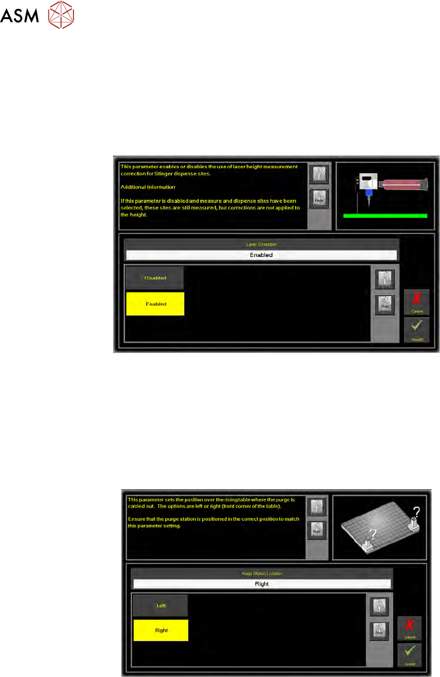
2.3.2.2 Laser Correction
Laser Correction uses laser height measurement correction at dispense and calibration sites.
When enabled, the laser takes a comparative reading at each programmed site. This data is
gathered to compensate for differences in board height across its upper surface and to provide cali-
bration data. The reading becomes a datum point for the placement of the nozzle tip, prior to dot
placement. If disabled, readings are taken but the correction is not performed; the system relies
upon accurate Z-Axis coordinates set in the parameter Stinger Dispense Gap.
1. To enable laser correction, select Laser Correction.
2. Select Enabled.
3. Select Accept.
2.3.2.3 Purge Station Location
Purge Station Location is the location at the front of the rising table where the purge station is
placed. At the start or end of a production run, the user may request a purge. Purging ensures that
the flow of adhesive is continuous and homogenous. The purge station contains a pot that collects
the purged adhesive; it can be located on the front left or front right corner of the rising table.
1. To set the location, select Purge Station Location.
2. Select the location where you are going to place the purge station (front Left or Right).
NOTE
The purge station is not placed at this time. The action above is to set the location in software.
3. Select Accept.
2 STINGER, A GUIDE TO ADHESIVE DOT DISPENSING
2.3 SOFTWARE INTERFACE
GUIDE TO ADHESIVE DOT DISPENSING STINGER 03/2021 23
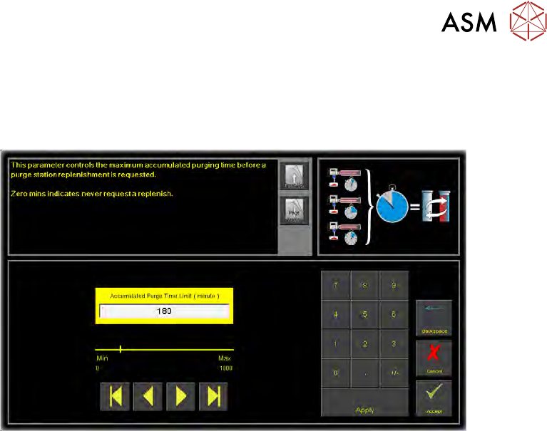
2.3.2.4 Accumulated Purge Time Limit
Accumulated Purge Time Limit is set to control the maximum accumulated purge time, before a
purge station replenishment is requested. After flagging the replenishment need, the user can open
the printhead front cover and examine the view port to decide if replenishment is needed.
The purge station lid is fitted so that it pivots inward when fixed to either side of the rising table; this
allows the pot to be removed with the station in-situ.
As the level of the adhesive in the purge station increases, an estimate of the amount of adhesive
purged (based on the programmed parameter - Accumulated Purge Time Limit) is made each time
a purge event occurs.
At the end of the purge, a wipe action takes place to clean the nozzle in the target.
1. Select Accumulated Purge TIme Limit.
2. Set a time limit.
3. Select Accept.
2 STINGER, A GUIDE TO ADHESIVE DOT DISPENSING
2.3 SOFTWARE INTERFACE
24 GUIDE TO ADHESIVE DOT DISPENSING STINGER 03/2021
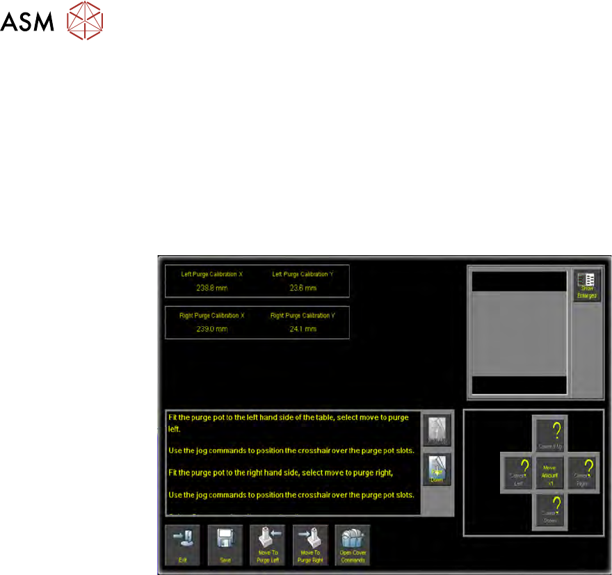
2.3.2.5 Calibrate Purge Pot Locations
Calibrate Purge Pot Locations allows the precise position of the purge station wiper target to be
programmed. Physically, its mechanical constraints and those of the table and the transport rails
determine the purge station placement. To enable the nozzle to be precisely placed, in the wiper
target, the station is placed correctly on the rising table front edge. The target location is measured
and programmed, from the centre of the wiper target cross to the centre of the camera reference
dot on the front rail.
1. Select Calibrate Purge Pot Locations.
A window with command buttons, a camera view vision window and set of nudge/move
amount (x1, x 10, x100) control buttons is displayed.
2. Select Open Cover Commands.
NOTE
The purge station must be seated correctly, fully down on the corner of the rising table, with
its barriers snugly fitting the front and side edges of the table.
3. Follow the on-screen instruction to, in turn, place the purge station in both the left hand side
front and right hand side front locations.
4. With the purge station in the left location; select Move To Purge Left. The camera moves
over the purge station in left hand location; the vision window displays an alignment crosshair.
5. If required, use the nudge/move buttons to align the crosshair over the purge station slots.
6. Select Open Cover Commands.
7. Fit the purge station to the right hand side.
8. Select Move To Purge Right.
9. Align the crosshair over the purge station slots.
NOTE
Use the Show Enlarged button to enlarge the vision window image for higher precision.
10. Select Save.
11. Select Exit.
12. Select Back.
13. Select Back.
14. Select Back.