ASM_Guide To Adhesive Dot Dispensing_Stinger_en_0321_online.pdf - 第34页
2 STINGER, A GUIDE TO ADHESIVE DOT DISPENSING 2.3 SOFTWARE INTERFACE 34 GUIDE TO ADHESIVE DOT DISPENSING STINGER 03/2021 Navigation buttons are available for the user to search for products in long lists, or to organise …
2 STINGER, A GUIDE TO ADHESIVE DOT DISPENSING
2.3 SOFTWARE INTERFACE
GUIDE TO ADHESIVE DOT DISPENSING STINGER 03/2021 33
3. Select Create Site.
4. Select Load Image.
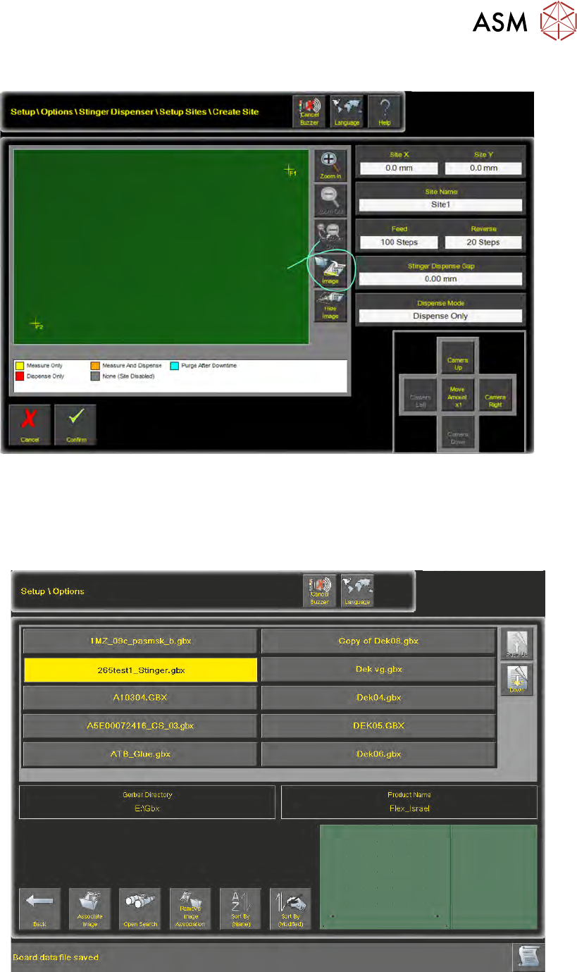
2.3.5 Load a Product Image
Loading an image loads a product representation onto the interface. Sites where adhesive dots are
to be deposited can be easily targeted, avoiding on-board features such as pads or tracks.
Select the required product from the table, the Gerber Data is replicated in the product image win-
dow at the bottom right of the page.
2 STINGER, A GUIDE TO ADHESIVE DOT DISPENSING
2.3 SOFTWARE INTERFACE
34 GUIDE TO ADHESIVE DOT DISPENSING STINGER 03/2021
Navigation buttons are available for the user to search for products in long lists, or to organise the
list by name or number. In addition, the user can make or remove associations with the image to a
product file.
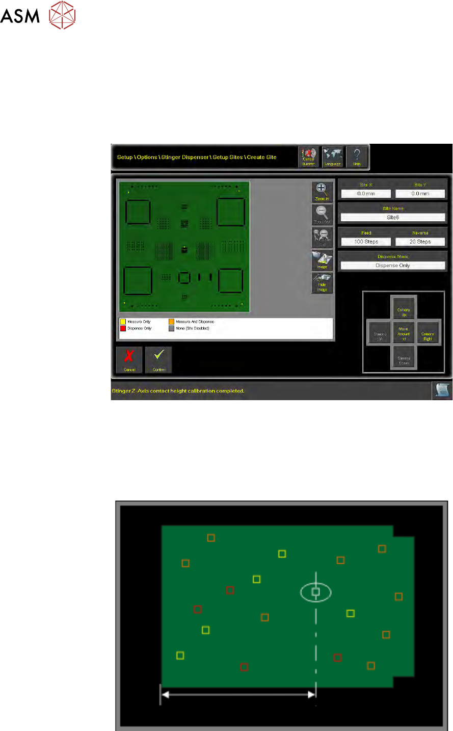
2.3.6 Create Sites
The selected product file image is loaded into the product image view on the Create Sites page of
the user interface.
Identify the area on the product image view, where the site is to be located, and mouse click the
area (point using a touch screen monitor) to create the site location. Alternatively, using the camera
jog functionality, the site location and hence the nozzle location is moved by jogging a factor of x1,
x10 or x100 move amounts.
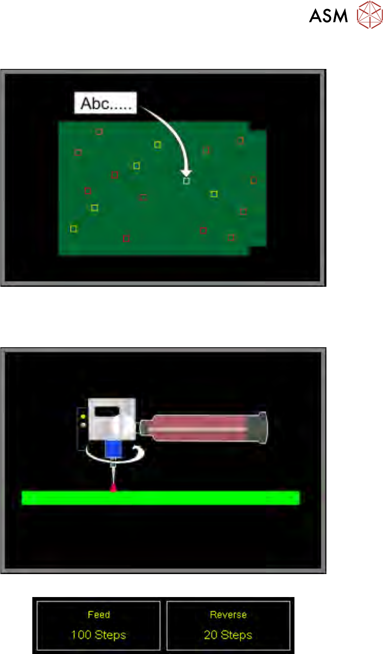
Site(s) can be placed in the correct location and edited:
1. Edit the Site X and Site Y coordinate parameters
2 STINGER, A GUIDE TO ADHESIVE DOT DISPENSING
2.3 SOFTWARE INTERFACE
GUIDE TO ADHESIVE DOT DISPENSING STINGER 03/2021 35
2. Assign a unique Site Name to each site
3. Programme for each site, the number of forward (Feed) and reverse auger feed steps.
When sites are selected, the parameter indicators Feed and Reverse show the number of
programmed steps for the auger movements.
4. Set the Stinger Dispense Gap
The dispense gap is the height between the nozzle tip and the upper surface of the product. It
is the height at which dispensing takes place. This can be any value in the range; 0 to 5mm;
zero is the top of the board. The larger the gap, the higher the adhesive dot dispensed. Typic-
ally the gap is set to between 1.5 and 2 times the nozzle inside diameter. For information on
nozzle inside diameters refer to nozzles in the introduction section of this manual.