ASM_Guide To Adhesive Dot Dispensing_Stinger_en_0321_online.pdf - 第41页
2 STINGER, A GUIDE TO ADHESIVE DOT DISPENSING 2.3 SOFTWARE INTERFACE GUIDE TO ADHESIVE DOT DISPENSING STINGER 03/2021 41 2.3.8 Calibrating Stinger Heights NOTE If the product is changed, or if the equipment has been repl…
2 STINGER, A GUIDE TO ADHESIVE DOT DISPENSING
2.3 SOFTWARE INTERFACE
40 GUIDE TO ADHESIVE DOT DISPENSING STINGER 03/2021
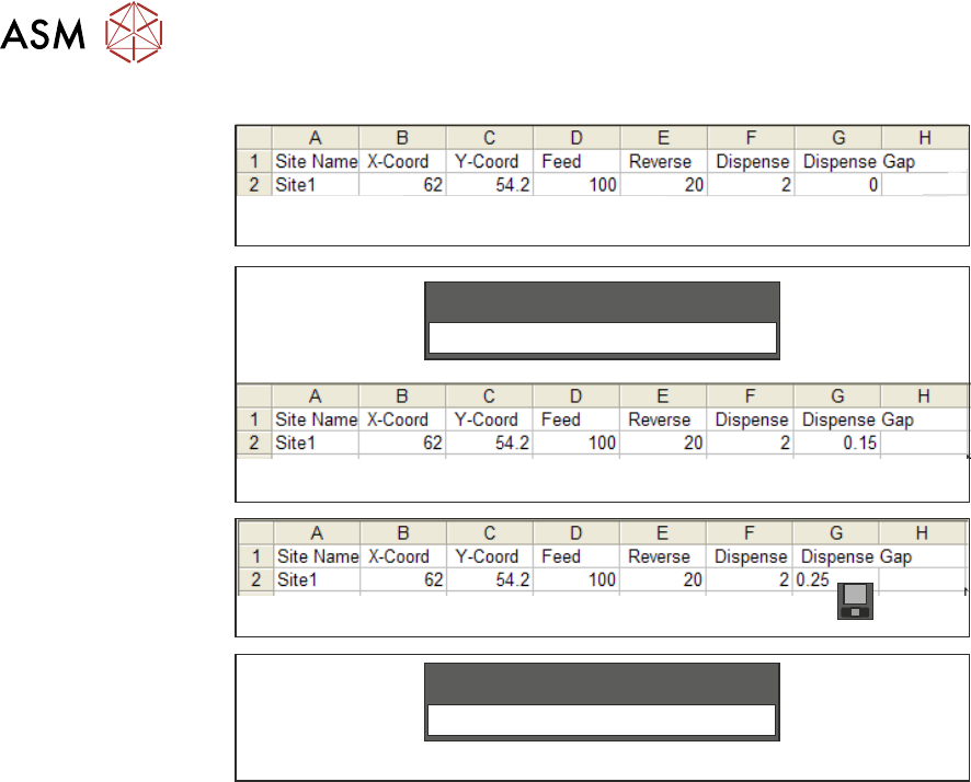
Figure 1
Figure 2
Figure 3
Figure 4
0.15
Dispense Gap
Save
0.25
Dispense Gap
Selecting Back twice returns control to the Ready page; data is stored on exit from this page.
2 STINGER, A GUIDE TO ADHESIVE DOT DISPENSING
2.3 SOFTWARE INTERFACE
GUIDE TO ADHESIVE DOT DISPENSING STINGER 03/2021 41
2.3.8 Calibrating Stinger Heights
NOTE
If the product is changed, or if the equipment has been replaced, or it is being set up for the first
time, performing a manual height calibration first, improves system accuracy as the contact height
is set up accurately. See the appendix for details.
This procedure relates to units that have the automatic calibration option.
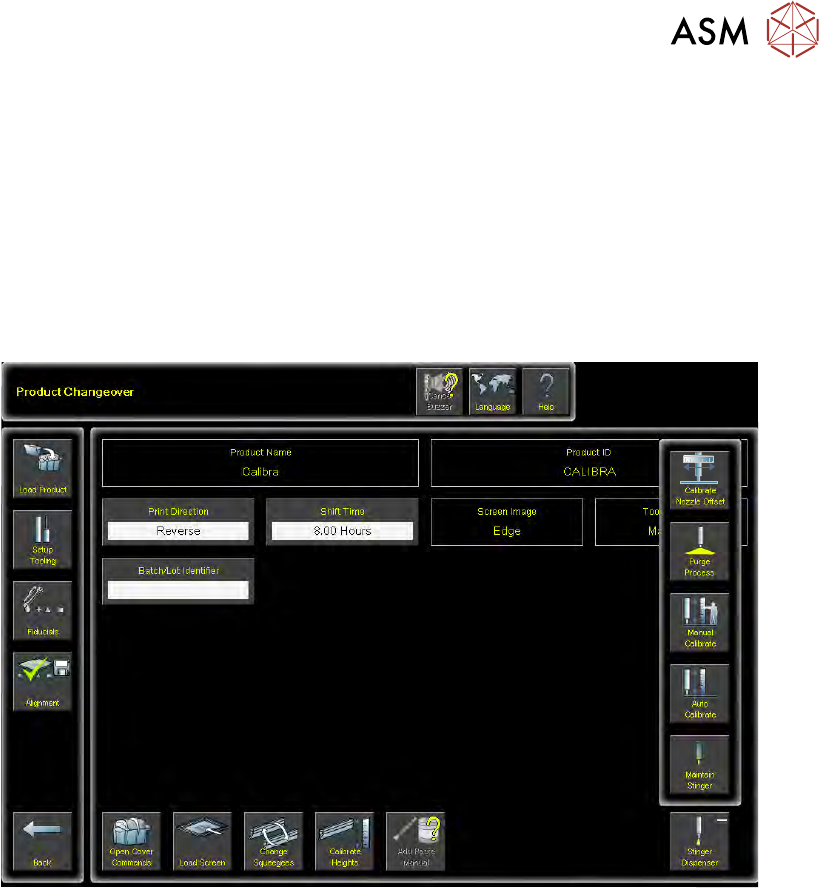
1. Select Product Changeover.
2. Select Stinger Dispenser.
3. Select Auto Calibrate.
The camera axis is driven to the calibration location and automatically jogs down until the nozzle
reaches the top surface of the product. At this point the laser does not register a change in reading
and the correct contact height is set. Because the idle height is set in a parameter Setup Product
\Options\Stinger Dispenser, there is no need to set the idle height as this difference (between
contact height and the set value for idle height) is maintained by the laser tracking the surface of
the product during printing.
NOTE
Laser range checks are only carried out after setting contact height in manual mode. If auto-cali-
bration fails, performing a manual calibration resets the laser range.
2.3.8.1 Siting The Calibration Point
Product is not always rectangular in shape and completely plane surfaced. There are often features
such as protruding edges and gaps in various places across the product. This means that users
must be aware of where to place the calibration point. The unit performs two distinct checks in one
action, they are:
●
Contact Height
●
Laser Range Checking
The unit defaults to the centre of the board or the purge over product point for its calibration co-
ordinates (shown in white outline). This may not be an appropriate location as the product may
have features that do not allow for both the nozzle, and the laser beam to be accommodated cor-
rectly.
2 STINGER, A GUIDE TO ADHESIVE DOT DISPENSING
2.3 SOFTWARE INTERFACE
42 GUIDE TO ADHESIVE DOT DISPENSING STINGER 03/2021
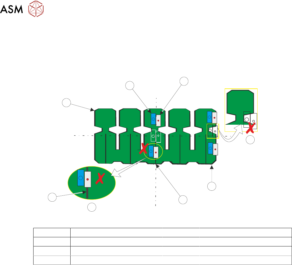
In the diagram, the unit is shown with two rectangles representing the laser (blue) and the nozzle
(grey). Three ‘potential’ locations have been shown, top centre and bottom. At the centre, (white
outline) the unit can make a good contact height check. However, when the unit moves from the
contact height position to the range location, on the right, the board edge is not straight, therefore
the laser may not be ‘seeing’ the upper surface of the product, as depicted by the black outlined
rectangles (see incorrect range location).
L
L
C
C
1
2
5
3
4
6
7
8
1 Nozzle 5 Incorrect Height Location
2 Incorrect Range Location 6 Gap
3 Range Locations 7 Product
4 Contact Height Positions 8 Laser
Similarly, a feature under the laser on the bottom location is centred over a gap in the board where
the laser beam passes through. The contact height cannot be set. The user must choose a location
similar to that of the top track, where both the range and height checks can be carried out success-
fully.