CP7 training(6.0) (1).pdf - 第105页
FK-9F98-27 CP-7 Series Traini ng Text for Service Engineers Edition 6.0 Chapter 6. Servo Pack Zero Ad justment and Gain / Motion Check [9/10] Gain T est T able *CP-742/3ME, CP-742/3E Note: This t able applies to applicat…
FK-9F98-27 CP-7 Series Training Text for Service Engineers
Edition 6.0 Chapter 6. Servo Pack Zero Adjustment and Gain / Motion Check [8/10]
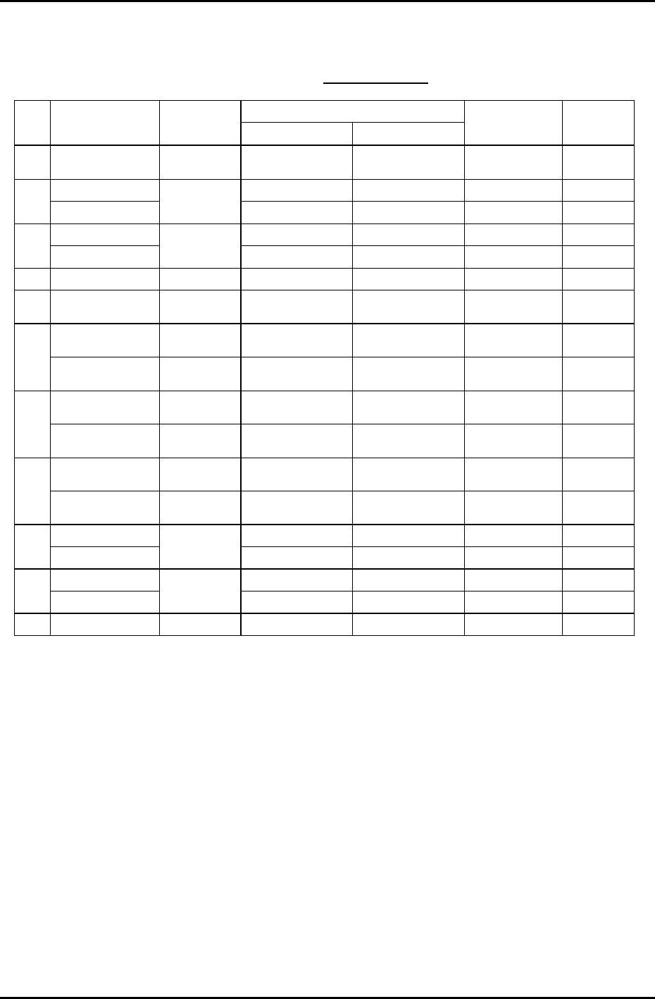
Gain Test Table
*CP-732/3E
Note: This table applies to application versions
T1.00a & higher
Value entered
Axis Parameter
Adj.
condition
Start End
Traverse time
(ms)
Overshoot
(pulse)
C Auto
Current counter
value
Start value
+12000
137.0 to 140.0 40 to 50
6K-230K UHi 10000 17100 46.0 to 49.0 0 to 10
X
IK-230K MID
Cam @ 0
10000 13000 46.0 to 49.0 0 to 10
5K-197.5K UHI 10000 17100 46.0 to 49.0 0 to 10
Y
500-197.5K MID
Cam @ 0
10000 13000 46.0 to 49.0 0 to 10
Z Auto Cam @ 0 1000 1595 46.0 to 49.0 0 to 5
PQ ROTATION 100 Cam @180 Current counter
value
Start value
+3600
34.5 to 37.5 0 to 10
0.4K-1.3K
ROT 100
Cam @180 Current counter
value
Start value
+1300
30.5 to 33.5 0 to 10
FQ
RETURN Cam @ 0 Current counter
value
Start value +450 12.5 to 15.5 0 to 10
ROTATION 100 Cam @180 Current counter
value
Start value
+3600
34.5 to 37.5 0 to 10
RQ
RETURN Cam @ 0 Current counter
value
Start value +450 12.5 to 15.5 0 to 10
ROTATION Cam @180 Current counter
value
Start value
+1200
12.0 to 15.0 0 to 10
NC
RETURN Cam @ 0 Current counter
value
Start value
+1200
25.0 to 28.0 0 to 10
5K-9K STD L 0 8250 77.0 to 80.0 0 to 10
D1
WEIGHT MEAS
Cam @ 0 &
Empty table
0 3000 54.0 to 57.0 0 to 10
5K-9K STD L 0 8250 77.0 to 80.0 0 to 10
D2
WEIGHT MEAS
Cam @ 0 &
Empty table
0 3000 54.0 to 57.0 0 to 10
NZ Auto Cam @ 0 4000 10750 46.0 to 49.0 0 to10
Enter 1 in [Cycle Mode] and 500 in [Timer] for all Axes.
Fuji Machine Mfg. Co., Ltd. (Okazaki)
SMT Equipment Quality Assurance Dept.
CS Section
6-8
FK-9F98-27 CP-7 Series Training Text for Service Engineers
Edition 6.0 Chapter 6. Servo Pack Zero Adjustment and Gain / Motion Check [9/10]
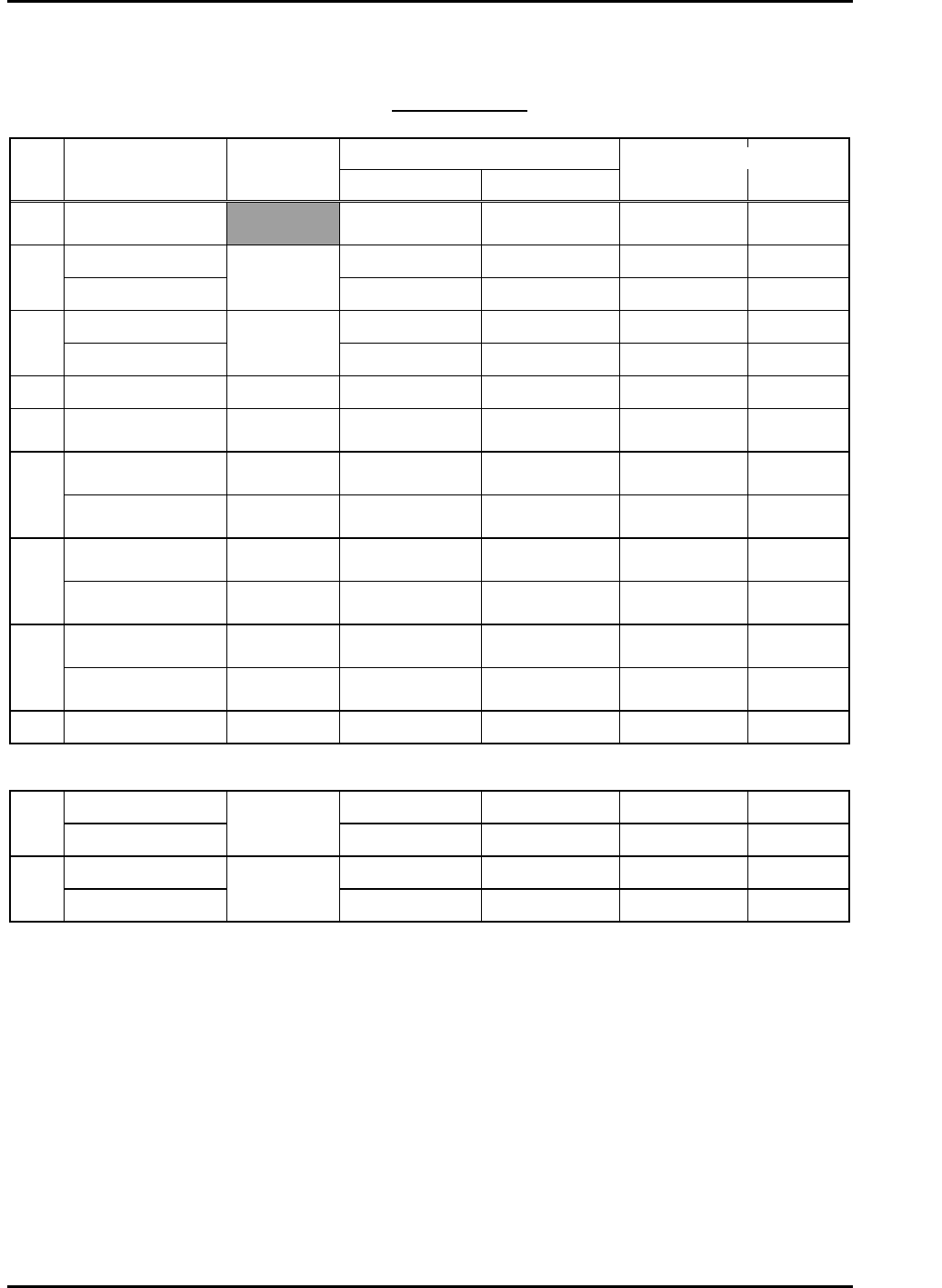
Gain Test Table
*CP-742/3ME, CP-742/3E
Note: This table applies to application versions T1.00a & higher
Value entered
Axis Parameter
Adj.
condition
Start End
Traverse time
(ms)
Overshoot
(pulse)
C Auto
Current counter
value
Start value
+12000
139.0 to 142.0 33 to 44
6K -10K UHi 10000 17100 46.0 to 49.0 0 to 10
X
2K-4K MID
Cam @ 0
10000 13000 46.0 to 49.0 0 to 10
6K-17K UHi 10000 17100 46.0 to 49.0 0 to 10
Y
2K-10K MID
Cam @ 0
10000 13000 45.0 to 48.0 0 to 10
Z 250lnf AUTO Cam @ 0 1000 1595 46.0 to 49.0 0 to 5
PQ ROTATION 100 Cam @180
Current counter
value
Start value
+3600
34.5 to 37.5 0 to 10
0.4-1.3K ROT 100 Cam @180
Current counter
value
Start value
+1300
30.5 to 33.5 0 to 10
FQ
RETURN Cam @ 0
Current counter
value
Start value +450 12.5 to 15.5 0 to 10
ROTATION 100 Cam @180
Current counter
value
Start value
+3600
34.5 to 37.5 0 to 10
RQ
RETURN Cam @ 0
Current counter
value
Start value +450 12.5 to 15.5 0 to 10
ROTATION Cam @180
Current counter
value
Start value
+1200
12.0 to 15.0 0 to10
NC
RETURN Cam @ 0
Current counter
value
Start value
+1200
25.0 to 28.0 0 to 10
NZ Auto Cam @ 0 4000 10750 46.0 to 49.0 0 to 10
CP-742/3ME • CP-742/3E
5K-9K STD L 0 8250 77.0 to 80.0 0 to 10
D1
WEIGHT MEAS
Cam @ 0 &
Empty table
0 3000 54.0 to 57.0 0 to 10
5K-9K STD L 0 8250 77.0 to 80.0 0 to 10
D2
WEIGHT MEAS
Cam @ 0 &
Empty table
0 3000 55.0 to 58.0 0 to 10
Enter 1 in [Cycle Mode] and 500 in [Timer] for all Axes.
Fuji Machine Mfg. Co., Ltd. (Okazaki)
SMT Equipment Quality Assurance Dept.
CS Section
6-9
FK-9F98-27 CP-7 Series Training Text for Service Engineers
Edition 6.0 Chapter 6. Servo Pack Zero Adjustment and Gain / Motion Check [10/10]
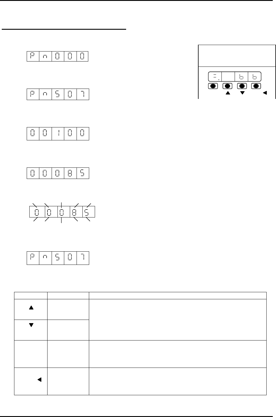
Using the Servo Pack Panel Operator
1. By pressing the MODE/SET key, select the constant setting mode.
2. Press the UP or DOWN key to set the User constant No.
(for instance, Pn507)
3. Press the DATA/SHIFT key for more than 1 second.
The present user constant data, which is set in step 2 will be displayed. “00100”
4. Press the UP or DOWN key to change the data. “00085”
The display gradually changes by pressing the down key.
5. Press the DATA/SHIFT key more than 1 second. The display flashes and the data will be
stored.
6. Press the DATA/SHIFT key more than one second. The display goes back to the User constant
No.
200V
YASKAWA
SERVOPACK
SSGDM-
DATA/
MODE/SET
Now, the user constant Pn507 is changed from 100 to 85. To change the data, repeat steps # 2
to # 6. Note: To move one place to the left, Press the DATA/SHIFT key for less than 1 second.
KEY NAME FUNCTION
Up Key
Down Key
• Press this key to display User setting or setting values.
• To increase a value, press the Up key.
• To decrease a value, press the Down key.
• Press UP&DOWN at the same time to reset servo alarms.
Mode/Set
Key
• Press this key to switch ”condition mode”, “supplement
function execution mode” “constant setting mode” and
“monitoring mode”.
Data/Shift
Key
• Press this key to display user settings and setting values.
• In the constant setting mode, use this key to change the
value (flashing no.) or to set data.
MODE/SET
DATA/
Fuji Machine Mfg. Co., Ltd. (Okazaki)
SMT Equipment Quality Assurance Dept.
CS Section
6-10