CP7 training(6.0) (1).pdf - 第106页
FK-9F98-27 CP-7 Series Traini ng Text for Service Engineers Edition 6.0 Chapter 6. Servo Pack Zero Adjustment and Gain / Motion Check [10/10] Using the Servo Pack Panel Operator 1. By pressing the MODE/SET key , select t…
FK-9F98-27 CP-7 Series Training Text for Service Engineers
Edition 6.0 Chapter 6. Servo Pack Zero Adjustment and Gain / Motion Check [9/10]
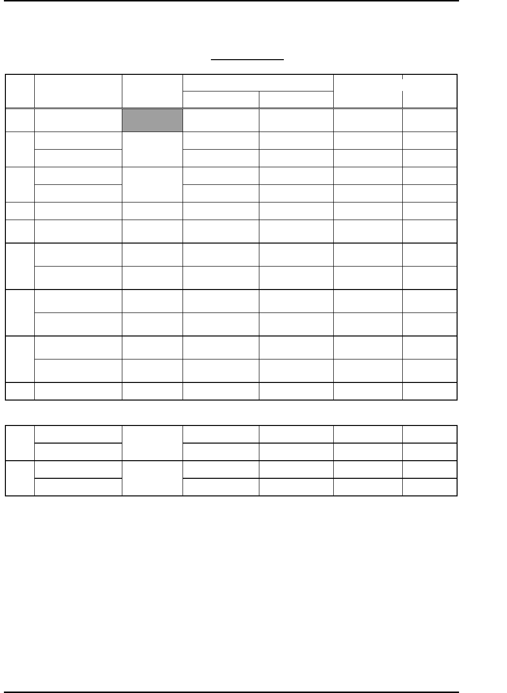
Gain Test Table
*CP-742/3ME, CP-742/3E
Note: This table applies to application versions T1.00a & higher
Value entered
Axis Parameter
Adj.
condition
Start End
Traverse time
(ms)
Overshoot
(pulse)
C Auto
Current counter
value
Start value
+12000
139.0 to 142.0 33 to 44
6K -10K UHi 10000 17100 46.0 to 49.0 0 to 10
X
2K-4K MID
Cam @ 0
10000 13000 46.0 to 49.0 0 to 10
6K-17K UHi 10000 17100 46.0 to 49.0 0 to 10
Y
2K-10K MID
Cam @ 0
10000 13000 45.0 to 48.0 0 to 10
Z 250lnf AUTO Cam @ 0 1000 1595 46.0 to 49.0 0 to 5
PQ ROTATION 100 Cam @180
Current counter
value
Start value
+3600
34.5 to 37.5 0 to 10
0.4-1.3K ROT 100 Cam @180
Current counter
value
Start value
+1300
30.5 to 33.5 0 to 10
FQ
RETURN Cam @ 0
Current counter
value
Start value +450 12.5 to 15.5 0 to 10
ROTATION 100 Cam @180
Current counter
value
Start value
+3600
34.5 to 37.5 0 to 10
RQ
RETURN Cam @ 0
Current counter
value
Start value +450 12.5 to 15.5 0 to 10
ROTATION Cam @180
Current counter
value
Start value
+1200
12.0 to 15.0 0 to10
NC
RETURN Cam @ 0
Current counter
value
Start value
+1200
25.0 to 28.0 0 to 10
NZ Auto Cam @ 0 4000 10750 46.0 to 49.0 0 to 10
CP-742/3ME • CP-742/3E
5K-9K STD L 0 8250 77.0 to 80.0 0 to 10
D1
WEIGHT MEAS
Cam @ 0 &
Empty table
0 3000 54.0 to 57.0 0 to 10
5K-9K STD L 0 8250 77.0 to 80.0 0 to 10
D2
WEIGHT MEAS
Cam @ 0 &
Empty table
0 3000 55.0 to 58.0 0 to 10
Enter 1 in [Cycle Mode] and 500 in [Timer] for all Axes.
Fuji Machine Mfg. Co., Ltd. (Okazaki)
SMT Equipment Quality Assurance Dept.
CS Section
6-9
FK-9F98-27 CP-7 Series Training Text for Service Engineers
Edition 6.0 Chapter 6. Servo Pack Zero Adjustment and Gain / Motion Check [10/10]
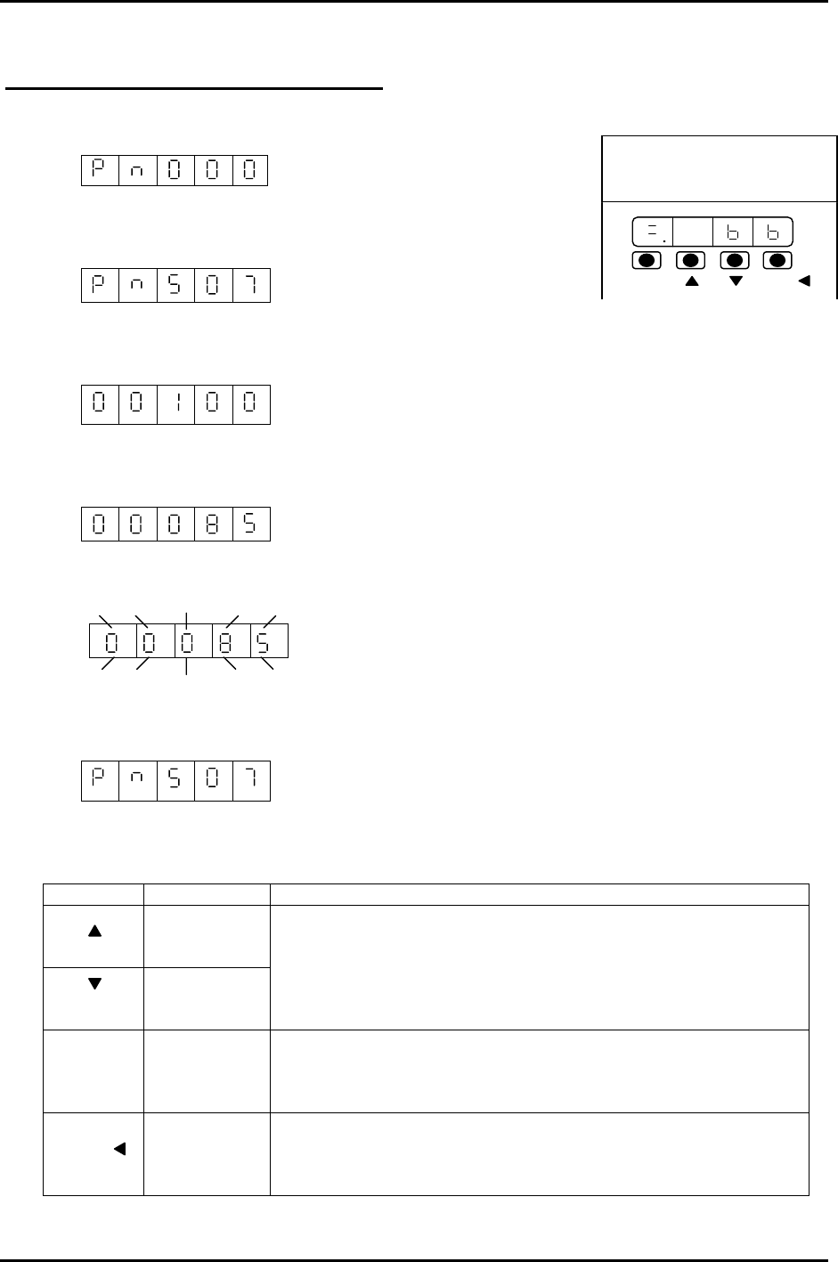
Using the Servo Pack Panel Operator
1. By pressing the MODE/SET key, select the constant setting mode.
2. Press the UP or DOWN key to set the User constant No.
(for instance, Pn507)
3. Press the DATA/SHIFT key for more than 1 second.
The present user constant data, which is set in step 2 will be displayed. “00100”
4. Press the UP or DOWN key to change the data. “00085”
The display gradually changes by pressing the down key.
5. Press the DATA/SHIFT key more than 1 second. The display flashes and the data will be
stored.
6. Press the DATA/SHIFT key more than one second. The display goes back to the User constant
No.
200V
YASKAWA
SERVOPACK
SSGDM-
DATA/
MODE/SET
Now, the user constant Pn507 is changed from 100 to 85. To change the data, repeat steps # 2
to # 6. Note: To move one place to the left, Press the DATA/SHIFT key for less than 1 second.
KEY NAME FUNCTION
Up Key
Down Key
• Press this key to display User setting or setting values.
• To increase a value, press the Up key.
• To decrease a value, press the Down key.
• Press UP&DOWN at the same time to reset servo alarms.
Mode/Set
Key
• Press this key to switch ”condition mode”, “supplement
function execution mode” “constant setting mode” and
“monitoring mode”.
Data/Shift
Key
• Press this key to display user settings and setting values.
• In the constant setting mode, use this key to change the
value (flashing no.) or to set data.
MODE/SET
DATA/
Fuji Machine Mfg. Co., Ltd. (Okazaki)
SMT Equipment Quality Assurance Dept.
CS Section
6-10
FK-9F98-27 CP-7 Series Training Text for Service Engineers
Edition 6.0 Chapter 7. Camera Adjustment [1/16]
Chapter 7 Camera Adjustment
Parts Cameras
Two CCD cameras are mounted on the machine for inspection of the parts picked at the first station.
The raw image is captured by the cameras and compared with part data to ensure that the part’s
dimensions are within specified tolerances.
Problems that arise from an incorrectly adjusted camera include displaced parts, high error rates, and
skewed parts. Some other examples of possible reasons for re-calibration are:
• Lens replacement
• Camera replacement
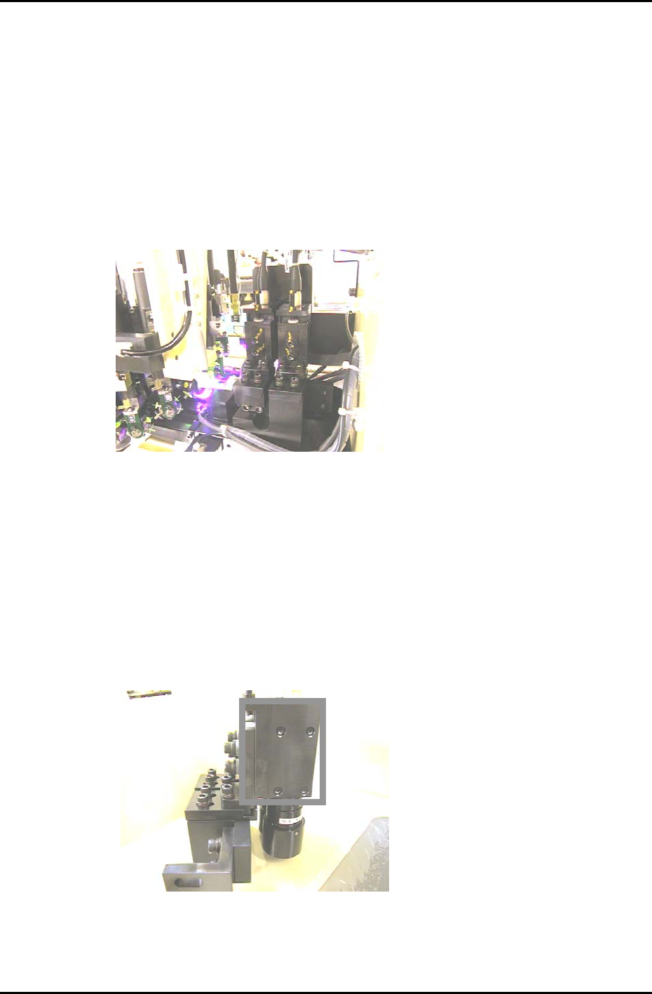
Figure 1
7.1 Parts Camera removal
1. With the machine power OFF, remove the video cables from the cameras.
2. Remove the cameras from the machine.
3. Remove the four mounting bolts from the right hand side of the bracket and carefully remove the
cameras. (The four bolts within the rectangle in figure 2). When replacing the camera, the torque
value for tightening these bolts is 0.98N.m. (10Kgf/cm)
Figure 2
Fuji Machine Mfg. Co., Ltd. (Okazaki)
SMT Equipment Quality Assurance Dept.
CS Section
7-1