CP7 training(6.0) (1).pdf - 第115页
FK-9F98-27 CP-7 Series Traini ng Text for Service Engineers Edition 6.0 Chapter 7. Cam era Adjustment [9 / 16] 7.9 Wide / Narrow Camera Skew and Resolution Adjustment 1. The camera skew adjustment is performed in ord er …
FK-9F98-27 CP-7 Series Training Text for Service Engineers
Edition 6.0 Chapter 7. Camera Adjustment [8/16]
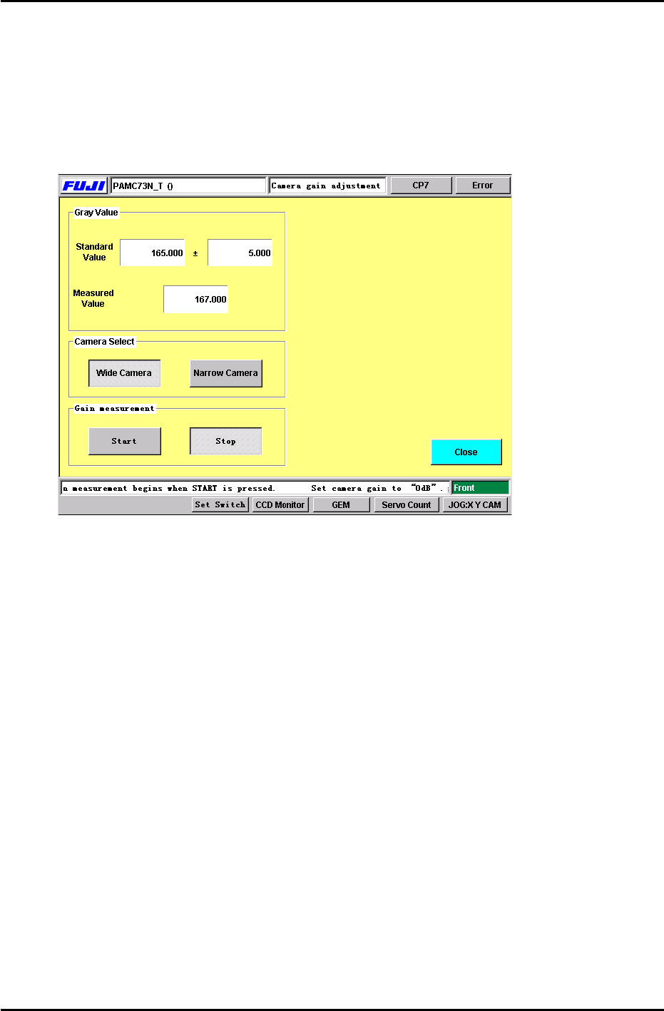
6. Select the camera to be adjusted and press the Start button. Adjust the camera gain trimmer so
the measured value matches the standard value displayed. (+/- 5.00) When completed, press
the stop button. (Figure 12) Carry out the same procedure for both cameras. (Wide and Narrow)
Note: Initially when the start button is pressed, a dialog box will appear briefly indicating not to
adjust the camera trimmer. After this dialog box disappears, it is OK to adjust the camera gain
trimmer.
FIGURE 12
7. Note: The above procedure only needs to be carried out once. However, this adjustment must be
repeated, if the camera gain trimmers are moved.
For further information, check the Fuji web-site for a supplement entittled “CP-7-Series: Adjusting
the Camera Gain”. Document No.: U0121-1.0E.
7.8 Nozzle Check (Temporary measurement)
1. After the camera gain adjustment, it is necessary to perform a nozzle check so the machine can
take a brightness level for the A1 nozzle reflective seal. Primarily, the A1 nozzle brightness
needs to be measured before the resolution can be measured. Otherwise, the vision system will
not be able to see the resolution jig.
Press: [Nozzle Check] → [Nozzle Size] or [Nozzle Bend] → Holder 1 → Enter → Start.
The brightness for the A1 nozzle must be measured in order to carry out the resolution
measurement performed in the next step. It is not necessary to install the other nozzles in
B1 to P1. A1 is the only nozzle position required at this time.
Fuji Machine Mfg. Co., Ltd. (Okazaki)
SMT Equipment Quality Assurance Dept.
CS Section
7-8
FK-9F98-27 CP-7 Series Training Text for Service Engineers
Edition 6.0 Chapter 7. Camera Adjustment [9/16]
7.9 Wide / Narrow Camera Skew and Resolution Adjustment
1. The camera skew adjustment is performed in order to align the camera with the X- and the Y- axes.
This is vital for determining accurate angular compensation at station 8 (FQ).
2. The camera resolution indicates the size of a pixel in the X and the Y direction. If the camera
resolution lies outside the specified range, the dimensions of the component inspected will not match
the data contained in the part data, and a vision processing error will occur.
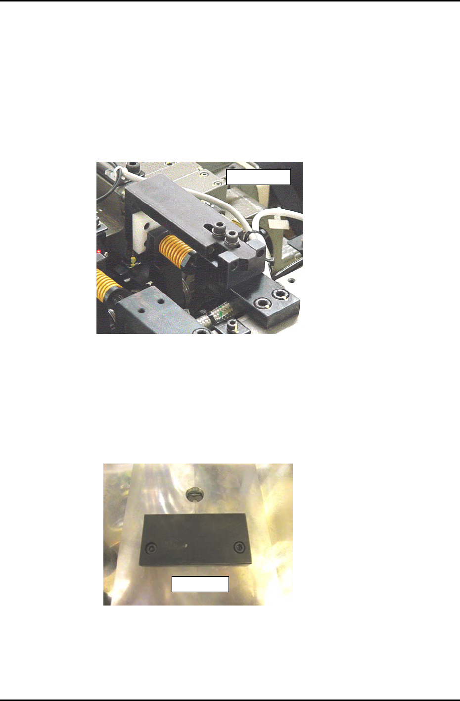
3. With the cam at 0 degrees, install the “cam lever spring lock jig” at station 8 in the cam box, as shown
in figure 13.
ADCPJ8120
Figure 13
4. Turn the pick up solenoid OFF, (Y032) with the cam at 0 degrees.
5. Put the wide camera inspection jig (ADCPJ 8100)on Head A, nozzle No.1.
6. Inch the jig to the 9
th
station and set at 195 degrees.
7. Remove the back up plates and attach the “XY Slide (magnet stand)” to the XY table, see Figure 14:
DCPJ0670
Figure 14
Fuji Machine Mfg. Co., Ltd. (Okazaki)
SMT Equipment Quality Assurance Dept.
CS Section
7-9
FK-9F98-27 CP-7 Series Training Text for Service Engineers
Edition 6.0 Chapter 7. Camera Adjustment [10/16]
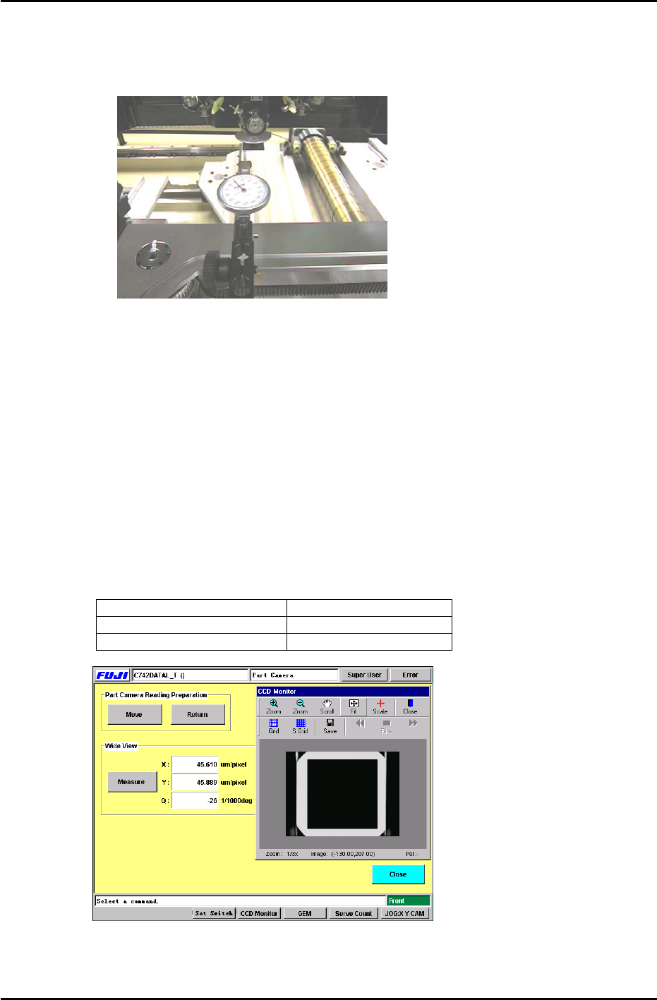
8. Set the dial gauge stand on the magnet stand and set the dial gauge tip to the horizontal flat edge of
the jig, see figure 15:
Figure 15
9. Set the X-axis inching speed to 1% and then inch the dial gauge tip from right to left across the
horizontal flat edge of the jig. Rotate the shaft until the dial gauge shows that the jig is parallel to the
X-axis. (Tol: 0 +/- 0.01mm)
10. Remove the dial gauge and inch the C-axis until the angle is 0 degrees and the jig is half way
between the 9
th
and 10
th
stations.
11. To automatically send the jig to the 5
th
station, use the following commands:
[MAINTENANCE] → [CALIBRATION] → [PARTS CAMERA RESOLUTION] → [MOVE] → START
12. To perform the measurement procedure press [MEASURE] → START.
13. The camera skew and resolution should be in the tolerances shown below:
Delta Q (skew) 0 +/- 50 (1/1000 deg.)
Wide camera resolution X 43.17 to 47.72 um/pixel
Wide camera resolution Y 43.40 to 47.96 um/pixel
Figure 16
14. If the resolution is out of range, loosen the lens cover and adjust the camera height. Afterwards,
reset the gap between the lens cover and the prism box to 0.5mm.
Fuji Machine Mfg. Co., Ltd. (Okazaki)
SMT Equipment Quality Assurance Dept.
CS Section
7-10