CP7 training(6.0) (1).pdf - 第117页
FK-9F98-27 CP-7 Series Traini ng Text for Service Engineers Edition 6.0 Chapter 7. Camera Adjustment [11 / 16] 15. T o adjust Delt a Q, loosen the delta Q positioning bolt s (see figure 15) and use a 2.5mm allen wrench t…
FK-9F98-27 CP-7 Series Training Text for Service Engineers
Edition 6.0 Chapter 7. Camera Adjustment [10/16]
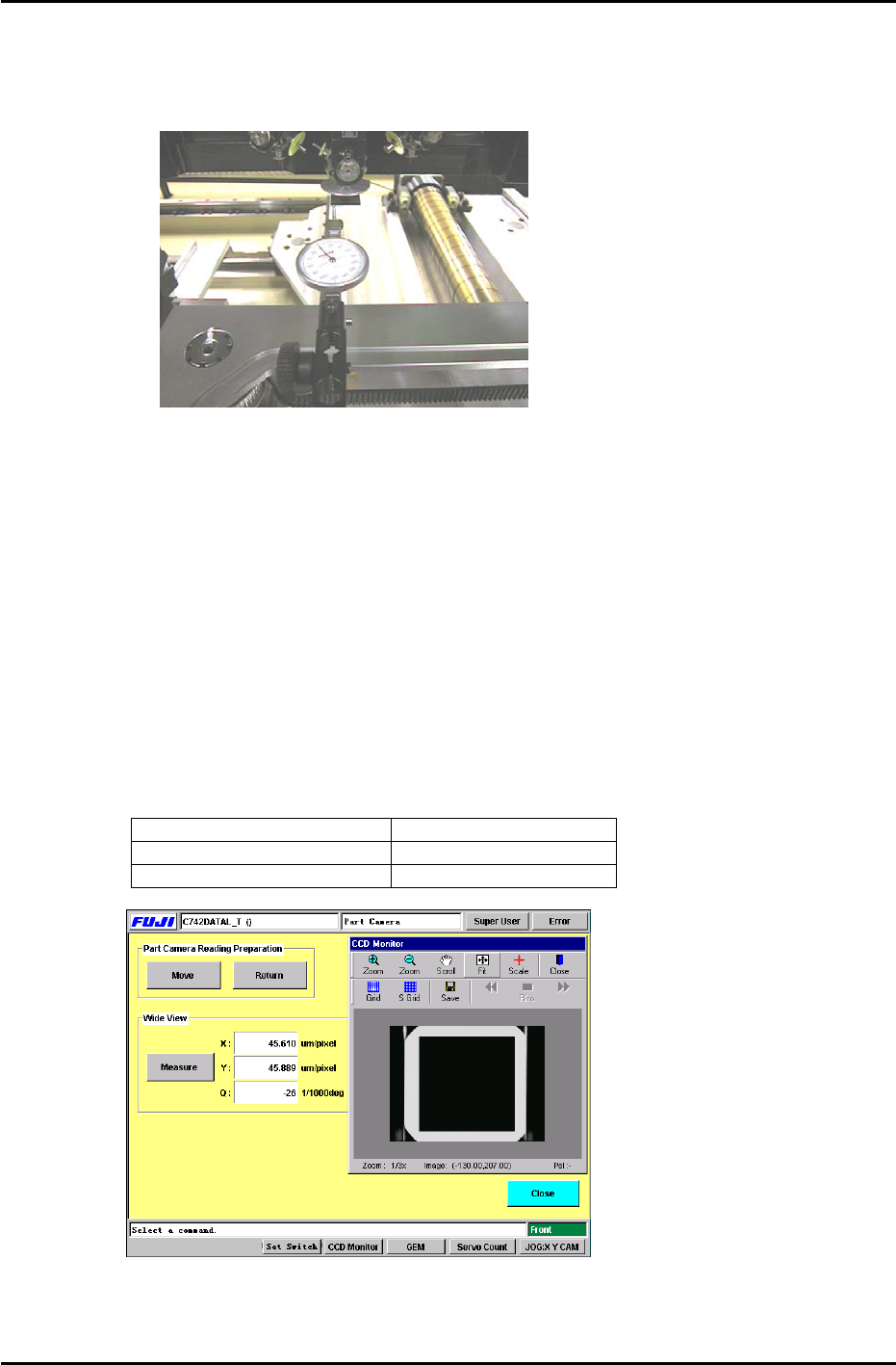
8. Set the dial gauge stand on the magnet stand and set the dial gauge tip to the horizontal flat edge of
the jig, see figure 15:
Figure 15
9. Set the X-axis inching speed to 1% and then inch the dial gauge tip from right to left across the
horizontal flat edge of the jig. Rotate the shaft until the dial gauge shows that the jig is parallel to the
X-axis. (Tol: 0 +/- 0.01mm)
10. Remove the dial gauge and inch the C-axis until the angle is 0 degrees and the jig is half way
between the 9
th
and 10
th
stations.
11. To automatically send the jig to the 5
th
station, use the following commands:
[MAINTENANCE] → [CALIBRATION] → [PARTS CAMERA RESOLUTION] → [MOVE] → START
12. To perform the measurement procedure press [MEASURE] → START.
13. The camera skew and resolution should be in the tolerances shown below:
Delta Q (skew) 0 +/- 50 (1/1000 deg.)
Wide camera resolution X 43.17 to 47.72 um/pixel
Wide camera resolution Y 43.40 to 47.96 um/pixel
Figure 16
14. If the resolution is out of range, loosen the lens cover and adjust the camera height. Afterwards,
reset the gap between the lens cover and the prism box to 0.5mm.
Fuji Machine Mfg. Co., Ltd. (Okazaki)
SMT Equipment Quality Assurance Dept.
CS Section
7-10
FK-9F98-27 CP-7 Series Training Text for Service Engineers
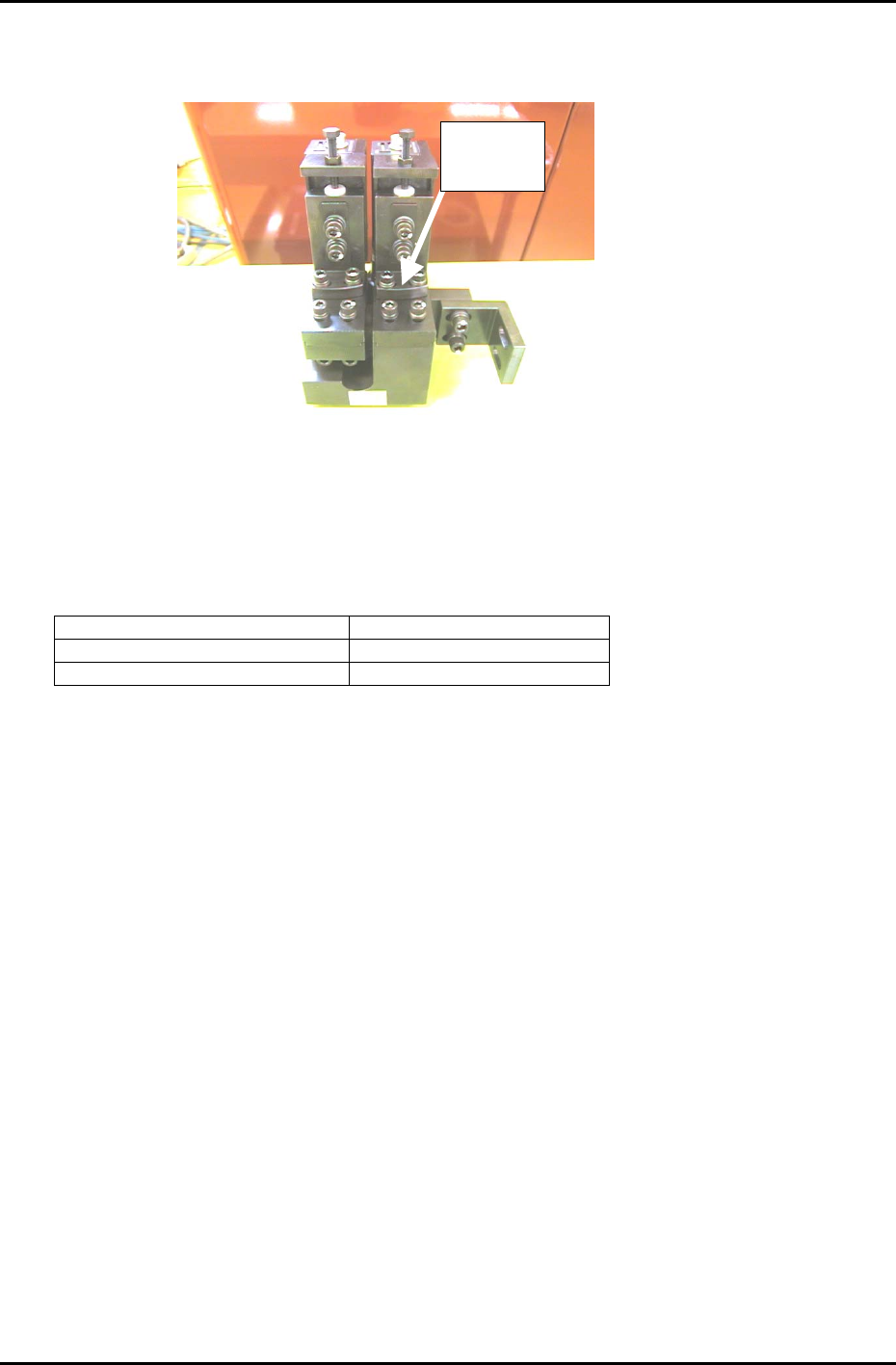
Edition 6.0 Chapter 7. Camera Adjustment [11/16]
15. To adjust Delta Q, loosen the delta Q positioning bolts (see figure 15) and use a 2.5mm allen
wrench to turn the eccentric bolt in order to achieve a target value of: 0 +/- 50 (1/1000 deg.)
Delta Q
positioning
Figure 17
16. Once the delta Q is set within tolerance:0 +/- 50 (1/1000 deg.) lock the delta Q positioning bolts with
an 8N.m torque wrench. After locking the bolts confirm that the delta Q value is still within tolerance.
17. Having finished the wide camera skew and resolution adjustment, repeat the procedure for the
narrow camera. Remember to use the narrow camera inspection jig (ADCPJ8110)and set the skew
and resolution values within the tolerances shown below:
Delta Q (skew) 0 +/- 50 (1/1000 deg.)
Narrow Camera Resolution X 11.81 to 13.06 um/pixel
Narrow Camera Resolution Y 11.88 to 13.13 um/pixel
18. Once the calibration procedure has been completed for both cameras, press [BACK] → START, and
the shaft will return to its original position.
19. With the cam at 0 degrees, remove the “cam lever spring lock jig” from the 8
th
station in the cam
box.
20. Remove the inspection jig from the No.1 slot of head A and replace any nozzles that have been
removed.
21. Place 1.0 to 2.5 mm nozzles in all holder locations and perform a nozzle center check in order to
update the “Base Nozzle” Calibration data.
Note: In order to register the BASE nozzle Calibration data, it is necessary to install 1.0 to 2.5 mm
nozzles in all (96) holder locations. This operation only needs to be done once. If the camera
position has been changed, it will be necessary to repeat the center measurement.
Fuji Machine Mfg. Co., Ltd. (Okazaki)
SMT Equipment Quality Assurance Dept.
CS Section
7-11
FK-9F98-27 CP-7 Series Training Text for Service Engineers
Edition 6.0 Chapter 7. Camera Adjustment [12/16]
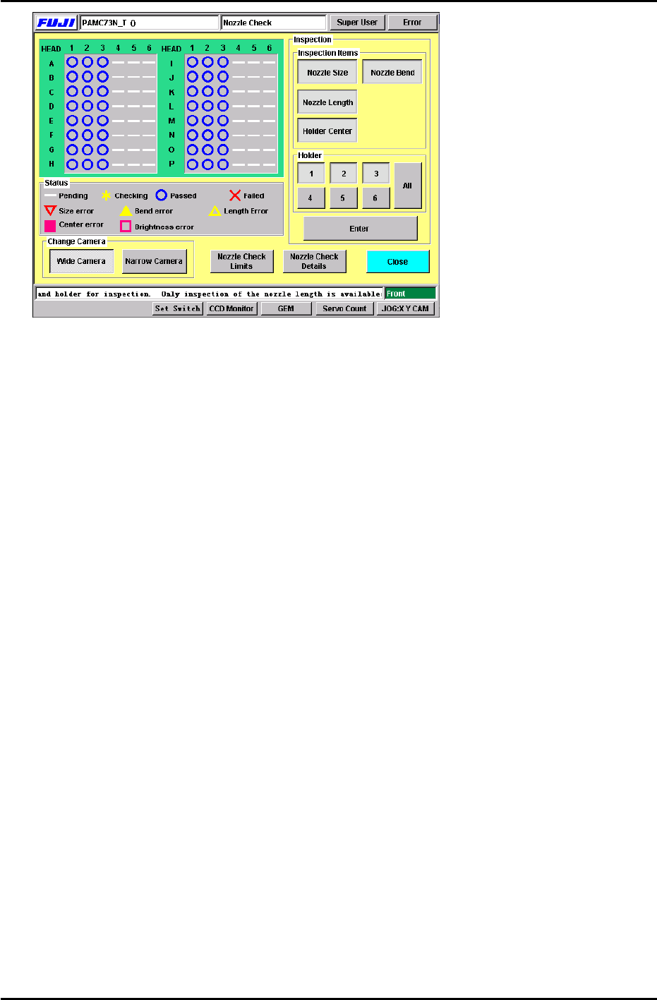
22. Receive the new Calibration Data to the host PC.
Figure 18
Fuji Machine Mfg. Co., Ltd. (Okazaki)
SMT Equipment Quality Assurance Dept.
CS Section
7-12