CP7 training(6.0) (1).pdf - 第118页
FK-9F98-27 CP-7 Series Traini ng Text for Service Engineers Edition 6.0 Chapter 7. Camera Adjustment [12 / 16] 22. Receive the new Calibration Data to the host PC. Figure 18 Fuji Machine Mfg. Co., Ltd. (Okazaki) SMT Equi…
FK-9F98-27 CP-7 Series Training Text for Service Engineers
Edition 6.0 Chapter 7. Camera Adjustment [11/16]
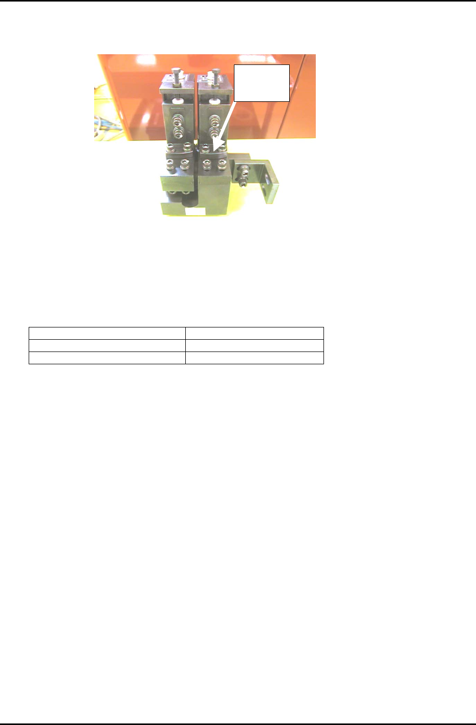
15. To adjust Delta Q, loosen the delta Q positioning bolts (see figure 15) and use a 2.5mm allen
wrench to turn the eccentric bolt in order to achieve a target value of: 0 +/- 50 (1/1000 deg.)
Delta Q
positioning
Figure 17
16. Once the delta Q is set within tolerance:0 +/- 50 (1/1000 deg.) lock the delta Q positioning bolts with
an 8N.m torque wrench. After locking the bolts confirm that the delta Q value is still within tolerance.
17. Having finished the wide camera skew and resolution adjustment, repeat the procedure for the
narrow camera. Remember to use the narrow camera inspection jig (ADCPJ8110)and set the skew
and resolution values within the tolerances shown below:
Delta Q (skew) 0 +/- 50 (1/1000 deg.)
Narrow Camera Resolution X 11.81 to 13.06 um/pixel
Narrow Camera Resolution Y 11.88 to 13.13 um/pixel
18. Once the calibration procedure has been completed for both cameras, press [BACK] → START, and
the shaft will return to its original position.
19. With the cam at 0 degrees, remove the “cam lever spring lock jig” from the 8
th
station in the cam
box.
20. Remove the inspection jig from the No.1 slot of head A and replace any nozzles that have been
removed.
21. Place 1.0 to 2.5 mm nozzles in all holder locations and perform a nozzle center check in order to
update the “Base Nozzle” Calibration data.
Note: In order to register the BASE nozzle Calibration data, it is necessary to install 1.0 to 2.5 mm
nozzles in all (96) holder locations. This operation only needs to be done once. If the camera
position has been changed, it will be necessary to repeat the center measurement.
Fuji Machine Mfg. Co., Ltd. (Okazaki)
SMT Equipment Quality Assurance Dept.
CS Section
7-11

FK-9F98-27 CP-7 Series Training Text for Service Engineers
Edition 6.0 Chapter 7. Camera Adjustment [12/16]
22. Receive the new Calibration Data to the host PC.
Figure 18
Fuji Machine Mfg. Co., Ltd. (Okazaki)
SMT Equipment Quality Assurance Dept.
CS Section
7-12
FK-9F98-27 CP-7 Series Training Text for Service Engineers
Edition 6.0 Chapter 7. Camera Adjustment [13/16]
Mark Camera Adjustments
7.10 Focus Adjustment
Note that before adjusting the mark camera the X0/Y0 and the Z0 adjustments must already be
completed, and the Calibration data input into the machine.
1. Set the switches at the rear of the amplifier as shown in figure 19:
SELECT SWITCH 1/30N
GAIN SWITCH OFF
SHUTTER SWITCH F
2. In the case of the CP732/733E attach the tooling pin jig ( ADCPJ8090) to the reference side of the
main conveyor.
SHUTTER
GAIN
SELECT
ON
OFF
1/30N
1/60N
1/30 I
F
DC IN/SYNC
VIDEO
DC IN12V
Figure 19
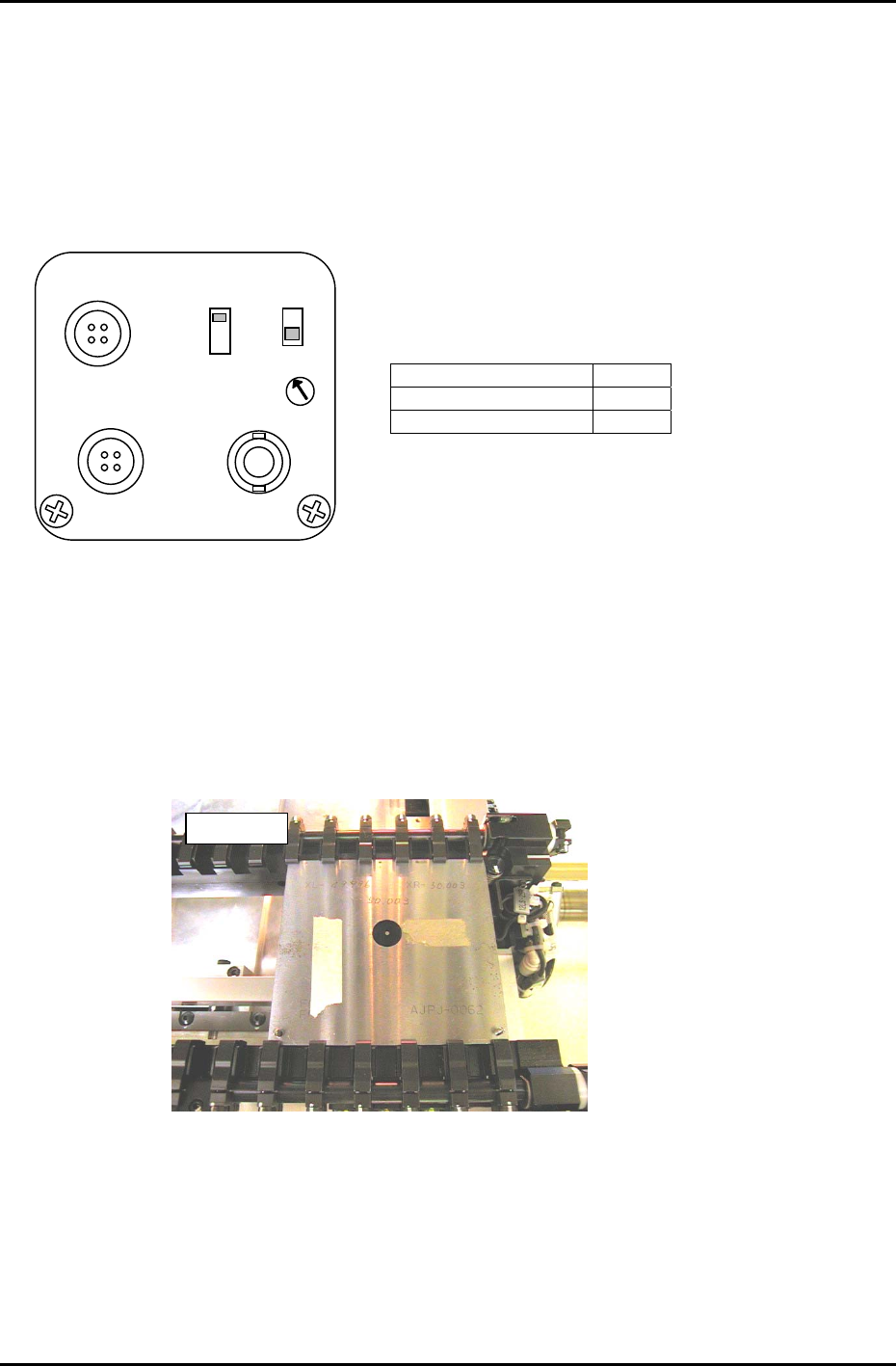
3. Clamp the fiducial jig plate in the main conveyor clamper. Make sure that the two tooling pins fit
smoothly into the two holes on the fiducial jig plate. See figure 20:
Note: For CP-732/733, use the tooling pin jig described in Sec. 3.7.2.
4. Move the fiducial jig plate to the mark read position using the following commands:
[MAINTENANCE] → [CALIBRATION] → [MARK CAMERA RESOLUTION] → [MOVE] → START
A message will display asking if X0/Y0 and Z0 has been completed. Press: [Yes]
The X, Y, and Z- axes will now move to their respective read positions.
A
JPJ0062
Figure 20
Fuji Machine Mfg. Co., Ltd. (Okazaki)
SMT Equipment Quality Assurance Dept.
CS Section
7-13