CP7 training(6.0) (1).pdf - 第126页
FK-9F98-27 CP-7 Series T raini ng T ext for Service Engineers Edition 6.0 Chapter 9, Miscellaneous Adjustments [4/6] 3. Park the D-axis pallets, a lign the D- axis pallet cover and D-axis escape positio n aluminum plate …
FK-9F98-27 CP-7 Series Training Text for Service Engineers
Edition 6.0 Chapter 9, Miscellaneous Adjustments [3/6]
9.3 D-axis Cover Installation
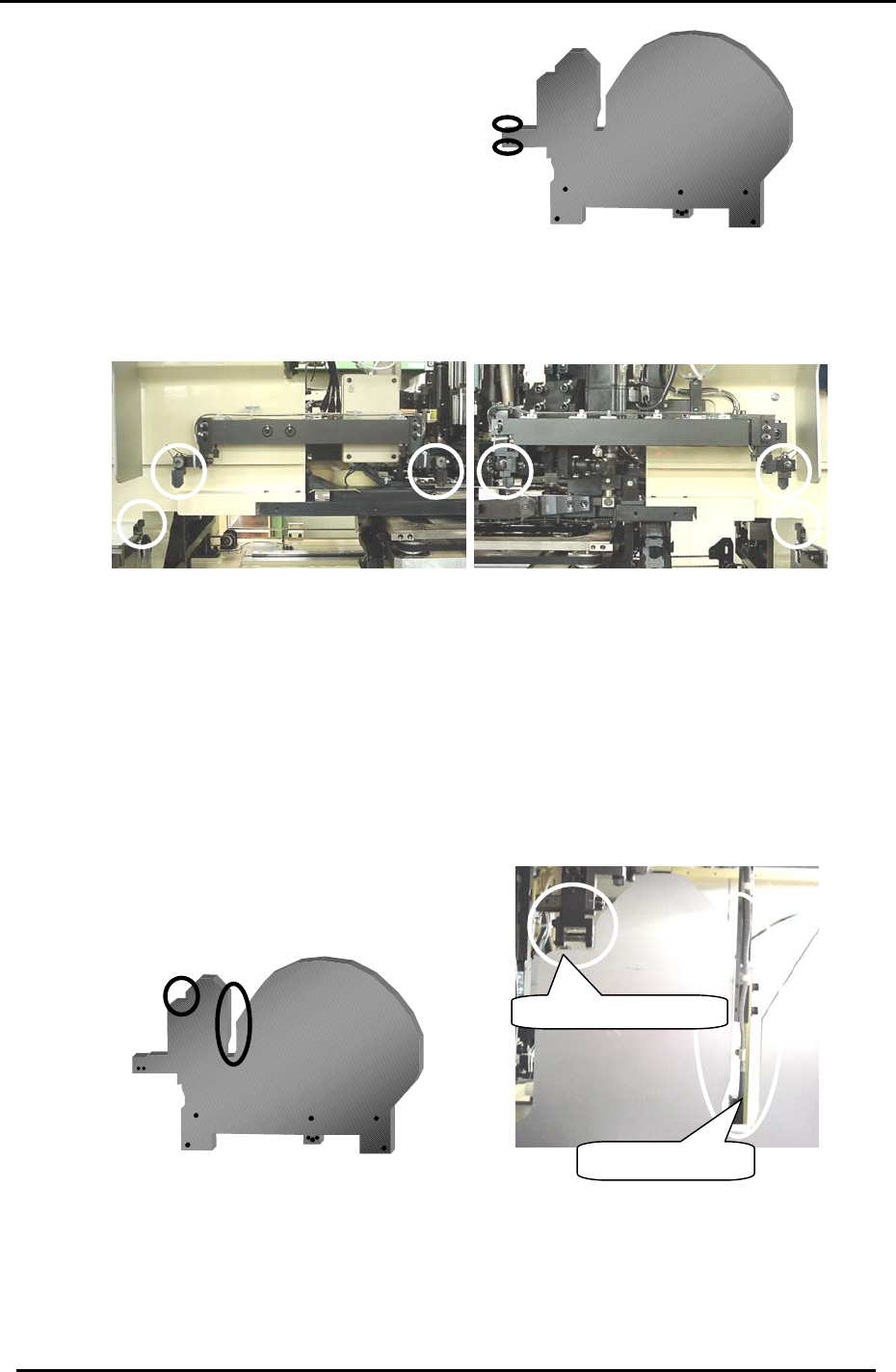
Install the 2 D-axis covers as follows:
1. After installation, verify that there is no interference between the pallet cover and the 6 sensors
as indicated in Fig. 4.
Figure 4
2. Inch the D-axis to move the pallet cover near the 1
st
station.
Note: Verify that there is no interference between the Pallet cover, Tape End sensor and the N
times feeding bracket as indicated in Fig.5.
T
a
p
e End senso
r
N times feedin
g
BKT
Figure 5
Fuji Machine Mfg. Co., Ltd. (Okazaki)
SMT Equipment Quality Assurance Dept.
CS Section
9-3
FK-9F98-27 CP-7 Series Training Text for Service Engineers
Edition 6.0 Chapter 9, Miscellaneous Adjustments [4/6]
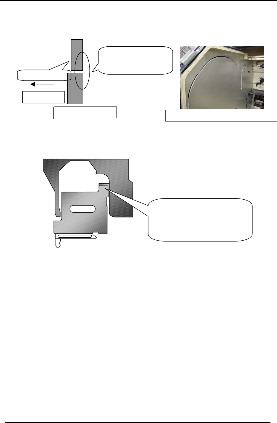
3. Park the D-axis pallets, align the D-axis pallet cover and D-axis escape position
aluminum plate as indicated in Fig.6.
4. Install as spacer jig on the D-axis, and adjust as indicated in Fig.7.
5. After adjustment, move the D-axis and verify that nothing interferes with the D-axis
pallet covers.
Cross- Section
Plates ali
g
n toward center of machine
Figure 7
Figure 6
Adjust the clearance between the
D-axis (at the escape position) and
the cover using a spacer jig.
(Jig No.: Z9526ADCPJ8640)
Pallet Side
Adjust the plates to
align toward the
center of the machine
.
D
-ax
i
s cover
Fuji Machine Mfg. Co., Ltd. (Okazaki)
SMT Equipment Quality Assurance Dept.
CS Section
9-4
FK-9F98-27 CP-7 Series Training Text for Service Engineers
Edition 6.0 Chapter 9, Miscellaneous Adjustments [5/6]
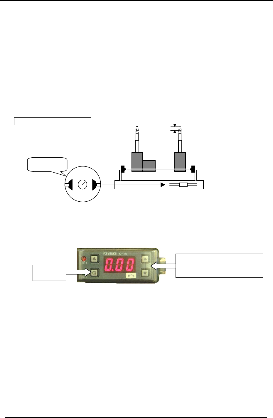
9.4 PCB Set Check Sensor Adjustment (CP-742/743(M)E)
1. Adjust the sensor BKT so that the light axis comes to the center of the reference pin
and secondary pin block hole.
2. Set the sensor so it turns OFF when both the reference and adjustable pins move
down 1.0 to 1.5mm.
3. As for the adjustable pin, the sensor should react at maximum, mid and minimum
pitches. Make sure that the green LED is always ON.
4. Check the sensor reaction in I/O
< I/O Æ Standard I/O Æ IN>
X059 PCB SET OK
1.0 to 1.5 mm
Figure 8
Set to MAX.
MIN
MAX
9.5 Oil Pressure Sensor Amp Adjustment
Up & Down Keys
To change setting values and set
output levels.
Setting Key
Follow the directions below to set the sensor amp operating parameters:
1. Press and hold the “A” key and Up arrow (▲)simultaneously to unlock the amp. (UNL)
2. Press and hold the setting key for 3 sec and set the pressure display to AP6.
3. Press the setting key to set the display to F-4.
4. Press the setting key to set the display to con.
5. Press the setting key twice to display H.
6. Press the up/down to set the high value to H 0.40.
7. Press the setting key twice to display L .
8. Press the up/down to set the low value to L 0.20.
9. Press the setting key to display P 000.
10. Press the setting key to view the current pressure value.
11. Press and hold the “A” key and Up arrow (▲) simultaneously to lock the amp. (LOC)
Fuji Machine Mfg. Co., Ltd. (Okazaki)
SMT Equipment Quality Assurance Dept.
CS Section
9-5