CP7 training(6.0) (1).pdf - 第138页
Chapter 12 Electrical System
FK-9F98-27 CP-7 Series Training Text for Service Engineers
Edition 6.0 Chapter 11. Absolute Encoder Recovery Procedure [4/4]
Absolute Encoders
Incremental encoders
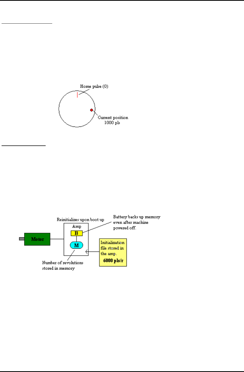
Let’s imagine that the resolution of the X-axis motor is 6000 pls., i.e. for every one revolution of the
motor, 6000 pulse are emitted. After each resolution is complete, that information is stored in the
amp’s memory. For example, the motor moves from the zero pulse position to the 25,000 pulse
position. This is equivalent to 4 full revolutions and another 1000 pulses. While the machine power is
on, we always know the motor position, because we measured the zero position upon booting up the
machine. Once the machine power is turned off, however, we lose that initial zero position, and when
we turn on the machine power again, the only thing the machine can remember is the 1000 pulses as
it is the number of pulses from the home pulse.
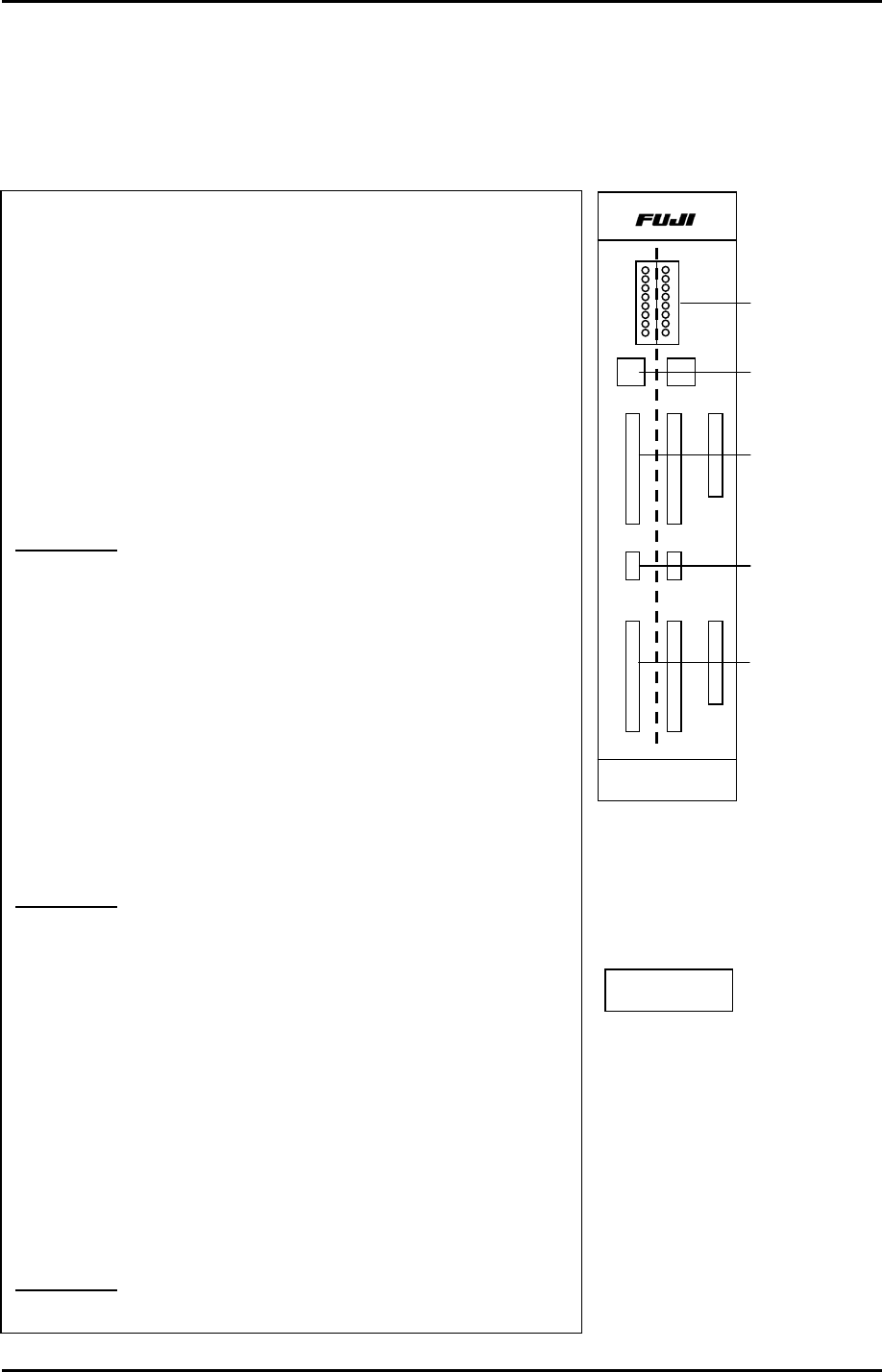
Absolute Encoders
Absolute encoders are similar in the method they use to count pulses, however, even after rebooting,
they still remember their absolute position. As each rotation of the motor is made, this information is
stored in the amp’s memory, e.g. 1 rev., or two revs.
In the above case, the motor travels 4 revolutions, and a further 1000 pulses. An initialization file,
stored inside the amp contains motor resolution info.(this is programmed at the factory or by
Yasukawa). After rebooting the motor, the amp reinitializes, reading the initialization file to multiply the
number contained in that file with the number of revolutions stored in the amp’s memory. The other
1000 pulses can be ascertained using the same method as the incremental encoders, i.e. reading the
motor’s current position.
Motors utilizing absolute encoders themselves are not any cheaper than those with incremental
encoders, however, their use eliminates the need for zero set sensor, dog, wire, pcb etc., thus lowering
costs.
Fuji Machine Mfg. Co., Ltd. (Okazaki)
SMT Equipment Quality Assurance Dept.
CS Section
11-4

Chapter 12
Electrical System
FK-9F98-27 CP-7 Series Training Text for Service Engineers
Edition 6.0 Chapter 12. Electrical System [1/10]
Chapter 12 Electrical System
12.1 Monitoring the I/O signals on CP-7 Series Machines
1. The I/O board is split into two sections. The right side
controls Input / Output 1 and the left side controls Input/
Output 2. Refer to the CP-7 Series System Reference Manual
(I/O Map for specific address locations)
2. Set the toggle switch UP to monitor Input signals.
Set the toggle switch DOWN to monitor Output signals.
3. Refer to the CP-7 Series System Reference Manual (I/O Map
for specific address locations) Once the desired address is
located, set the rotary dip switch accordingly.
Example 1:
To check the (input) signal from “Start Switch 1”:
1. Go to the I/O map in the CP-7 Series System Reference
Manual to find the address for Start Switch 1. Address X000.
2. Next, set the rotary dip switch for the Input- 1 side according
to the table on the next page. Dip Sw. = 0
3. Set the toggle switch UP for Input –1. (right side)
4. Press the front side start button and LED 0 will also flash on
the I/O board.
Example 2:
To check the (input) signal from the Back Up Pin
check sensor.
1. Go to the I/O map to find the address for the back up pin
check . Address X07B.
2. Next, set the rotary dip switch for the Input- 2 side according
to the table on the next page. Dip Sw. = 5
3. Set the toggle switch UP for Input –2.
4. Flag the back up pin check sensor and LED 3 will also flash
on the I/O board.
Example 3:
Fiducial lamp ON signal. (Output)
I/O - 1
0
7
I/O - 2
HIMC-1623B
Input/Output
Signal LEDs
Rotary Dip
Switches
Input signals
Toggle Switches
Up = Input
Down = Output
Output signals
I/O PCB
Fuji Machine Mfg. Co., Ltd. (Okazaki)
SMT Equipment Quality Assurance Dept.
CS Section
12-1