CP7 training(6.0) (1).pdf - 第140页
FK-9F98-27 CP-7 Series T raini ng T ext for Service Engineers Edition 6.0 Chapter 12. Electrical System [2/10] Fuji Machine Mfg. Co., Ltd. (Okazaki) SMT Equipment Quality Assurance Dept. CS Section 12-2 Refer to I/0 Map …
FK-9F98-27 CP-7 Series Training Text for Service Engineers
Edition 6.0 Chapter 12. Electrical System [1/10]
Chapter 12 Electrical System
12.1 Monitoring the I/O signals on CP-7 Series Machines
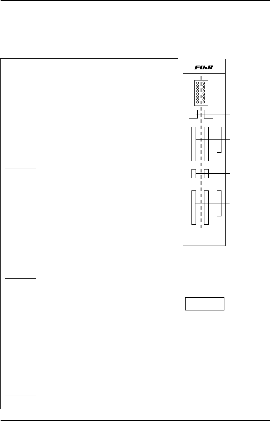
1. The I/O board is split into two sections. The right side
controls Input / Output 1 and the left side controls Input/
Output 2. Refer to the CP-7 Series System Reference Manual
(I/O Map for specific address locations)
2. Set the toggle switch UP to monitor Input signals.
Set the toggle switch DOWN to monitor Output signals.
3. Refer to the CP-7 Series System Reference Manual (I/O Map
for specific address locations) Once the desired address is
located, set the rotary dip switch accordingly.
Example 1:
To check the (input) signal from “Start Switch 1”:
1. Go to the I/O map in the CP-7 Series System Reference
Manual to find the address for Start Switch 1. Address X000.
2. Next, set the rotary dip switch for the Input- 1 side according
to the table on the next page. Dip Sw. = 0
3. Set the toggle switch UP for Input –1. (right side)
4. Press the front side start button and LED 0 will also flash on
the I/O board.
Example 2:
To check the (input) signal from the Back Up Pin
check sensor.
1. Go to the I/O map to find the address for the back up pin
check . Address X07B.
2. Next, set the rotary dip switch for the Input- 2 side according
to the table on the next page. Dip Sw. = 5
3. Set the toggle switch UP for Input –2.
4. Flag the back up pin check sensor and LED 3 will also flash
on the I/O board.
Example 3:
Fiducial lamp ON signal. (Output)
I/O - 1
0
7
I/O - 2
HIMC-1623B
Input/Output
Signal LEDs
Rotary Dip
Switches
Input signals
Toggle Switches
Up = Input
Down = Output
Output signals
I/O PCB
Fuji Machine Mfg. Co., Ltd. (Okazaki)
SMT Equipment Quality Assurance Dept.
CS Section
12-1
FK-9F98-27 CP-7 Series Training Text for Service Engineers
Edition 6.0 Chapter 12. Electrical System [2/10]
Fuji Machine Mfg. Co., Ltd. (Okazaki)
SMT Equipment Quality Assurance Dept.
CS Section
12-2
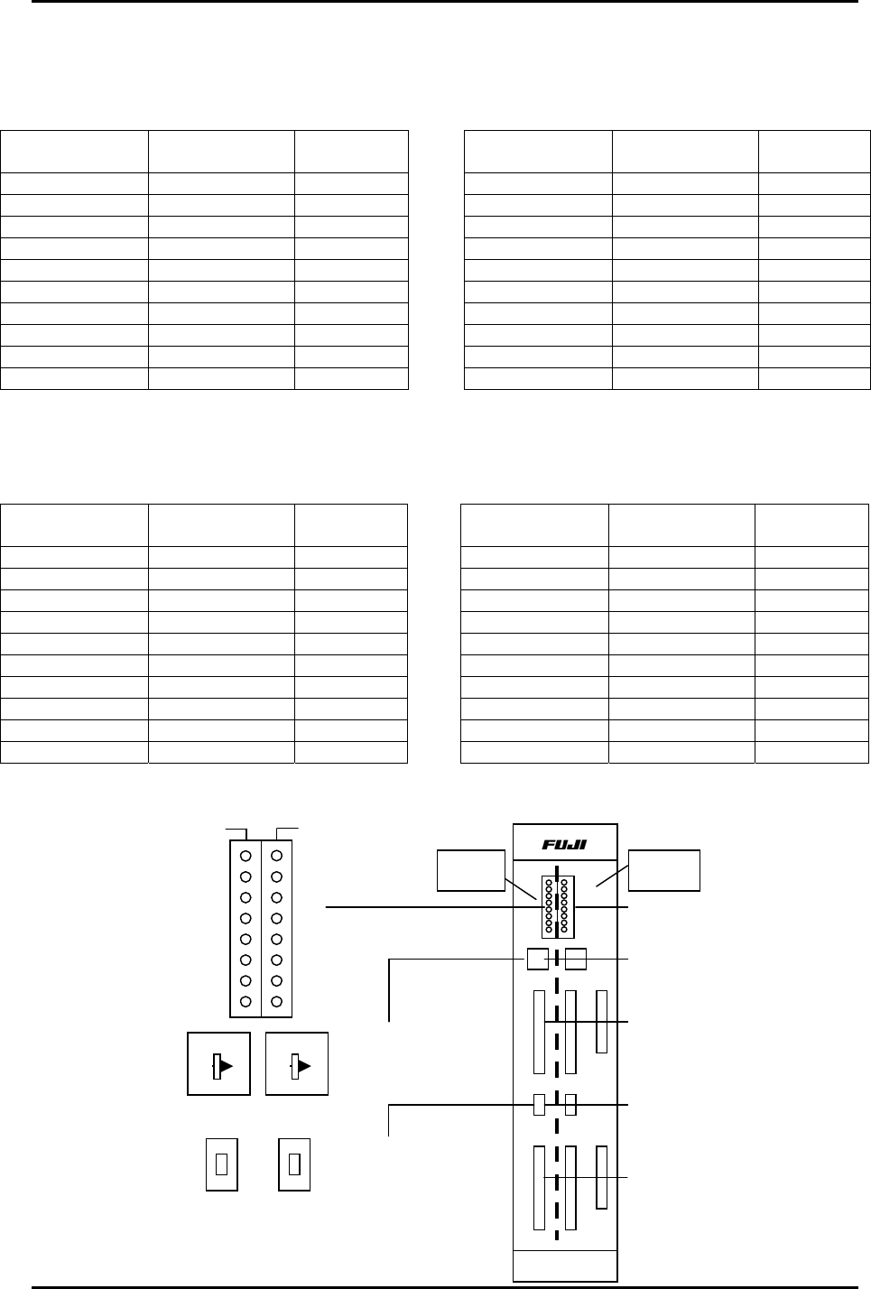
Refer to I/0 Map in the System Reference Manual for address descriptions.
Input - 2
Rotary Dip
Switch Position
I/0
Address
Green LED
0 X050 ~ X057 0 ~ 7
1 X058 ~ X05F 0 ~ 7
2 X060 ~ X067 0 ~ 7
3 X068 ~ X06F 0 ~ 7
4 X070 ~ X077 0 ~ 7
5 X078 ~ X07F 0 ~ 7
6 X080 ~ X087 0 ~ 7
7 X088 ~ X08F 0 ~ 7
8 X090 ~ X097 0 ~ 7
9 X098 ~ X09F 0 ~ 7
Input - 1
Rotary Dip
Switch Position
I/0
Address
Green LED
0 X000 ~ X007 0 ~ 7
1 X008 ~ X00F 0 ~ 7
2 X010 ~ X017 0 ~ 7
3 X018 ~ X01F 0 ~ 7
4 X020 ~ X027 0 ~ 7
5 X028 ~ X02F 0 ~ 7
6 X030 ~ X037 0 ~ 7
7 X038 ~ X03F 0 ~ 7
8 X040 ~ X047 0 ~ 7
9 X048 ~ X04F 0 ~ 7
Output - 2
Rotary Dip
Switch Position
I/0
Address
Green LED
0 Y050 ~ Y057 0 ~ 7
1 Y058 ~ Y05F 0 ~ 7
2 Y060 ~ Y067 0 ~ 7
3 Y068 ~ Y06F 0 ~ 7
4 Y070 ~ Y077 0 ~ 7
5 Y078 ~ Y07F 0 ~ 7
6 Y080 ~ Y087 0 ~ 7
7 Y088 ~ Y08F 0 ~ 7
8 Y090 ~ Y097 0 ~ 7
9 Y098 ~ Y09F 0 ~ 7
Output - 1
Rotary Dip
Switch Position
I/0
Address
Green LED
0 Y000 ~ Y007 0 ~ 7
1 Y008 ~ Y00F 0 ~ 7
2 Y010 ~ Y017 0 ~ 7
3 Y018 ~ Y01F 0 ~ 7
4 Y020 ~ Y027 0 ~ 7
5 Y028 ~ Y02F 0 ~ 7
6 Y030 ~ Y037 0 ~ 7
7 Y038 ~ Y03F 0 ~ 7
8 Y040 ~ Y047 0 ~ 7
9 Y048 ~ Y04F 0 ~ 7
0
1
2
3
4
5
6
7
In
p
ut / Out
p
ut - 1
In
p
ut / Out
p
ut - 2
(Green LEDs)
Input / Output – 1
Rotary Dip Switch
Input / Output – 2
Rotary Dip Switch
Toggle Switches
Up = Input
Down = Output
HIMC-1623B
0
7
Input/Output
Signal LEDs
Rotary Dip
Switches
In
p
ut si
g
nals
Out
p
ut si
g
nals
Input / Output – 1
Up = Input
Down = Output
Input / Output – 2
Up = Input
Down = Output
I/O -1 I/O -2
0
1
2
3
4
5
6
8
9
7
0
1
2
3
4
5
6
8
9
7
FK-9F98-27 CP-7 Series Training Text for Service Engineers
Edition 6.0 Chapter 12. Electrical System [4/10]
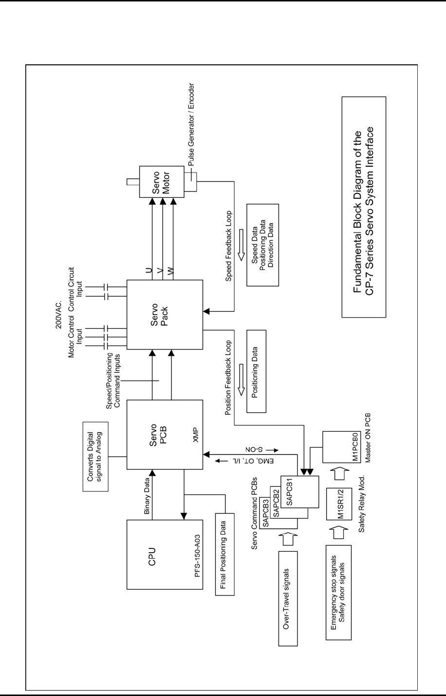
12.2 Servo System Interface
Fuji Machine Mfg. Co., Ltd. (Okazaki)
SMT Equipment Quality Assurance Dept.
CS Section
12-4