CP7 training(6.0) (1).pdf - 第144页
FK-9F98-27 CP-7 Series T raini ng T ext for Service Engineers Edition 6.0 Chapter 12. Electrical System [8/10] 12.5 The Absolute Encoder System A brief introduction into the workings of the “Absolute Encoder” 1. The moto…

FK-9F98-27 CP-7 Series Training Text for Service Engineers
Edition 6.0 Chapter 12. Electrical System [7/10]
12.4 Fuses and Batteries
Fuses
*** Refer to the electrical schematic parts list for fuse type and order number.
Qty Rating Location Comments
2 250ma Control Box 3 Face of Safety Relay 1 &2 (M1SR1/M1SR2)
2 500ma Control Box 3 Inside Safety Relay housing (F1)
2 100ma Control Box 3 Inside Safety Relay housing (si2-F2)
3 3.2A Control Box 2 CN PCB M1F1~3
1 4.0A Control Box 2 CN PCB M1F4
2 2.0A Servo Box 2 FU-DL1,2 (outside connection PCB)
2 2.0A Left side rear cam pillar FU-HL1,2 (outside connection PCB)
2 2.0A Operation Box 1 FU-HR1,2 (outside connection PCB)
2 2.0A D2-axis (Top) FU-RL1,2 (outside connection PCB)
2 2.0A D1-axis (Top) FU-RR1,2 (outside connection PCB)
3 2.0A Left side front cam pillar FU-LLD1,2,3 (outside connection PCB)
3 2.0A Right side front cam pillar FU-RLD1,2,3 (outside connection PCB)
3 2.0A Servo Box 1 FU-CAM1,2,3 (outside connection PCB)
1 3.0A Control Box 2 Master ON PCB (Fuse 1) M1PCB0
1 1.0A Control Box 2 Master ON PCB (Fuse 2) M1PCB0
1 10.0A Vacuum Box Thermal Fuse 10A/84C. (M1F5) Vacuum pump
1 10.0A Vacuum Box Thermal Fuse 10A/84C. (M1F6) Ring blow pump
Batteries
Note: The only replaceable batteries on CP7 series machines are used by each of the 11 servo
amplifiers. Refer to the electrical schematic parts list for battery type and order number.
Use CAUTION not to confuse the battery type required for each servo amplifier.
Refer to the Mechanical Reference Manual for the correct replacement procedure.
Fuji Machine Mfg. Co., Ltd. (Okazaki)
SMT Equipment Quality Assurance Dept.
CS Section
12-7
FK-9F98-27 CP-7 Series Training Text for Service Engineers
Edition 6.0 Chapter 12. Electrical System [8/10]
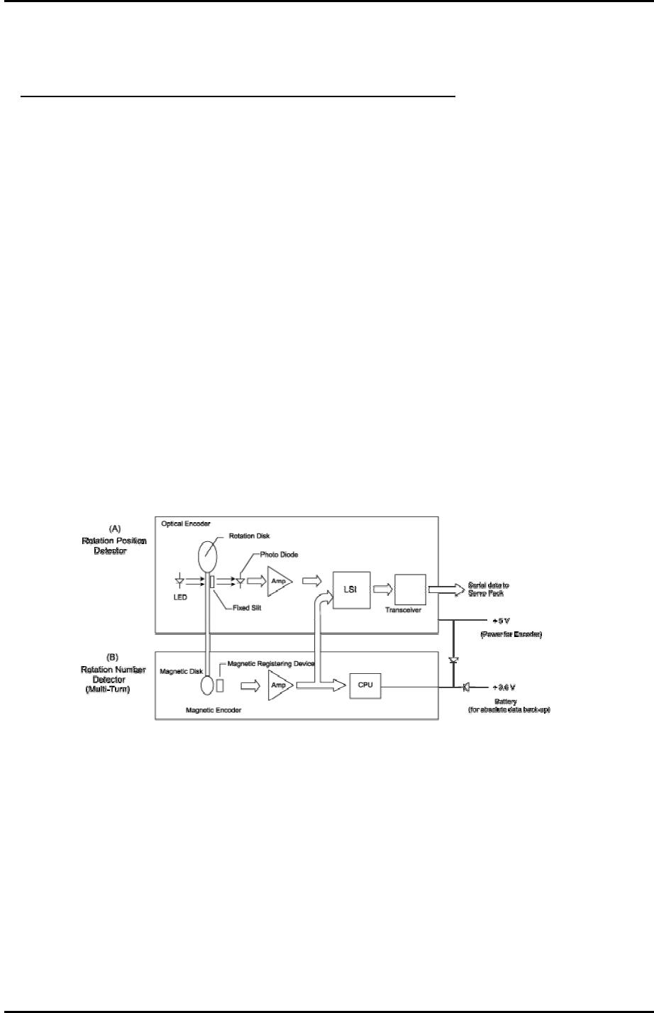
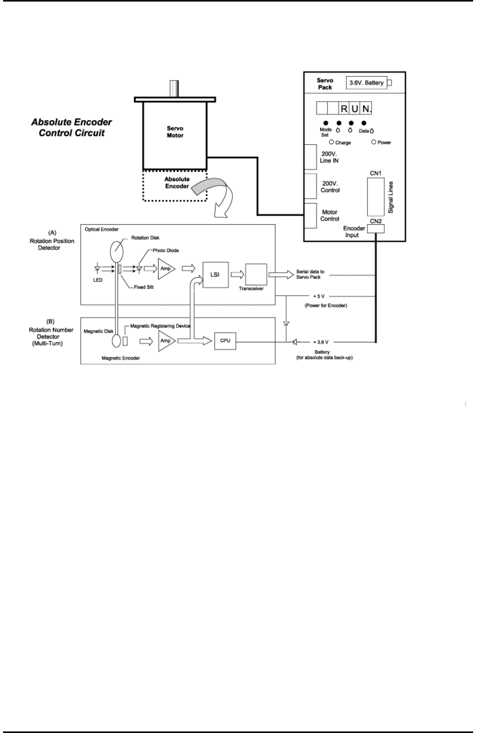
12.5 The Absolute Encoder System
A brief introduction into the workings of the “Absolute Encoder”
1. The motor shaft position within 1 revolution is monitored at (A).
2. The total number of rotations is counted at (B) and stored at the CPU.
3. The total number of rotations stored in the CPU will be cleared during encoder set-up.
4. There is a counting function (for rotational data) and serial communication circuit in the LSI.
(Large scale integration)
5. Pulses from A & B generated by disk rotation will be counted in LSI, and the absolute position
(the total number of rotations (B) + the position within 1 rotation (A) is transmitted based on
requests from the controller.
6. When the encoder cable is disconnected, the voltage supplied from the encoder power supply
(+ 5 V) and the back-up battery (+3.6 V) will be cut, and the total number of rotations will be
cleared.
7. There are two basic error conditions that will occur at the servo pack.
a.: “A . 81” will appear if the encoder cable has been disconnected for any reason. (motor, cable,
servo pack exchange etc..)
b.: “A . CC” will appear if the PN-205 servo pack parameter is accidentally changed. (PN-205 sets
the multi-turn limit of the encoder disk)
8. It is important that the user does not disconnect the encoder cable (cutting the circuit between
the servo pack and motor encoder) If the circuit is cut, it is necessary to reset the absolute
encoder according to the procedure outlined in Chapter 11.
Fuji Machine Mfg. Co., Ltd. (Okazaki)
SMT Equipment Quality Assurance Dept.
CS Section
12-
8
FK-9F98-27 CP-7 Series Training Text for Service Engineers
Edition 6.0 Chapter 12. Electrical System [9/10]
Fuji Machine Mfg. Co., Ltd. (Okazaki)
SMT Equipment Quality Assurance Dept.
CS Section
12-
9