CP7 training(6.0) (1).pdf - 第30页
FK-9F98-27 CP-7 Series T raini ng T ext for Service Engineers Edition 6.0 Chapter 3. X, Y , Z and D-axes Adjustm ent [16/36] 3.9 Z -axis Adjustment and Calibration Dat a Setting Equipment Checklist 1- 3mm L-wrench 1- 4mm…
FK-9F98-27 CP-7 Series Training Text for Service Engineers
Edition 6.0 Chapter 3. X, Y, Z and D-axes Adjustment [15/36]
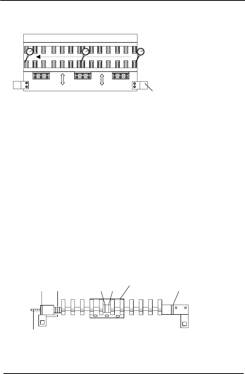
4. After the positioning has been completed in step 3, an alignment check of the reference rail in
the X-direction is necessary. Carry out the alignment check as indicated in Fig 18.
(Tolerance: within 0.1mm.)
Reference rail
* Loosen 13 bolts
*
*
*
*
*
*
*
*
*
*
*
*
*
Clamping cylinder
Figure 18
5. Check the following positions again, after completing step 4, to ensure they remain within
tolerance.
3-8.1 (Part 2) – Reference and Adjustable Rail Alignment in the Y direction
3-8.1 (Part 3) – Origin Pin To Claw
3.8.4 (Part 4) Mechanical Lock Ring Adjustment (CP-742/743(M)E)
1. On the reference rail, check that the gap between the white plastic washer and the far right clamper
bracket is less than 0.3mm. If not, loosen the mechanical lock and the bolts on the far right clamper
bracket, then adjust the position of the clamp rod until the gap closes.
2. Check that the center base of the reference rail is pulled right up against the lip of the reference rail.
Check that a 0.03mm feeler gauge cannot go into the gap between the two.
3. Confirm all of the claws on the reference rail are loose and then loosen the mechanical lock.
4. Lock the reference rail at its unclamped position.
5. With the reference rail unclamped, lock the four bolts in rotation with a 2N.m torque wrench.
6. For details of the location of various parts described above see Fig.19.
Fixed Rail of the X/Y Clamper
Spring
Mechanical lock
Washers 2 and 3
Washer 1
Center Base
Clamper Rod
Figure 19
7. Finally clamp and unclamp the reference rail to check the clamping balance between the left and
right clamping brackets. If there is an imbalance, repeat steps 3 to 5 above until a balance is
achieved.
Fuji Machine Mfg. Co., Ltd. (Okazaki)
SMT Equipment Quality Assurance Dept.
CS Section
3-15
FK-9F98-27 CP-7 Series Training Text for Service Engineers
Edition 6.0 Chapter 3. X, Y, Z and D-axes Adjustment [16/36]
3.9 Z -axis Adjustment and Calibration Data Setting
Equipment Checklist
1- 3mm L-wrench
1- 4mm T-wrench
1- Tension Meter
1- 1N.m torque wrench with 2mm attachment
1- 0.2mm feeler gauge
1- 2.5mm
T
-wrench
Note: The table must be level before making Z-axis adjustments.
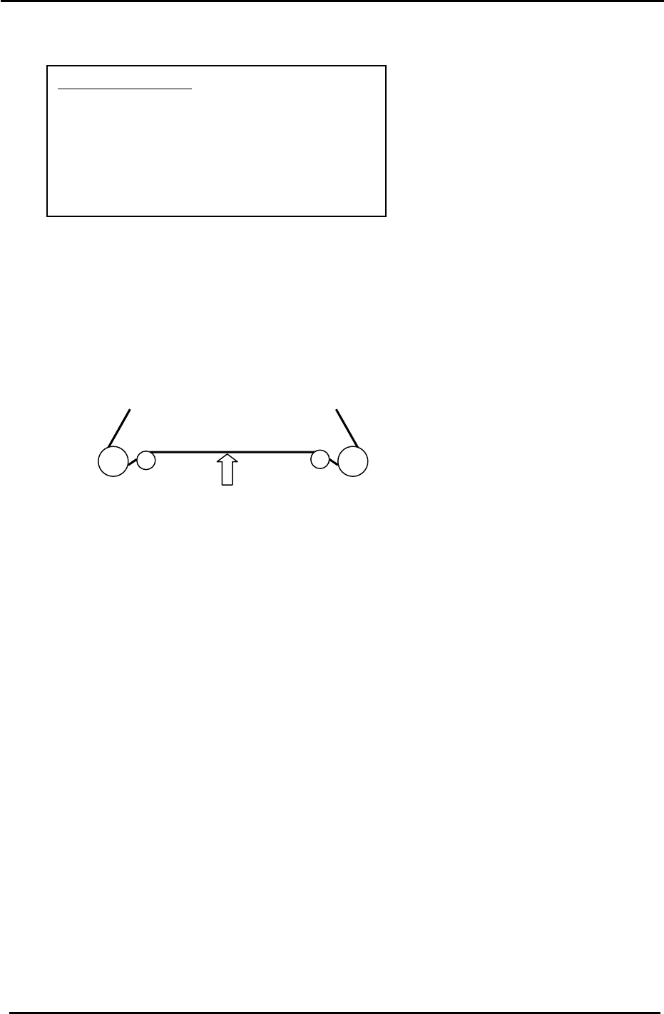
1. Set the tension of the Z-axis timing belt as follows:
CP-742/743(M)E = 64 +/- 2 Hz.
CP-732/733E = 119 +/- 2 Hz.
Measure the belt at a position where the span is the longest (front or back)
Measuring point
Figure 20
2. Remove the minus OT flag for the Z-axis.
3. Lower the servo pack gain value to 30. (Pn100) for CP-732/733E
4. Loosen the mechanical lock at the Z-axis drive pulley. (make sure the motor shaft turns freely)
5. Inch the Z servo count to – 900 pulses.
6. Lower the Z-axis table toward the (–) mechanical stopper and insert a 0.2mm feeler gauge
between the stopper and base of the table. (stopper at upper left side of table)
7. Lock the four securing bolts for the mechanical lock with a 1N.m torque wrench.
8. Check that the pulse count is close to – 900 when using the 0.2mm gap gauge.
9. Attach the – OT flag with the pulse count at – 500 pulses.
10. To set the software travel limit, find the pulse count where the minus OT sensor just turns ON.
Set the Z Min limit position as follows:
Press: [Maintenance] → [Calibration] → [Travel Limits] → [Minimum Limit Z]
Note: Set the Maximum limit after the loader adjustment has been completed.
(Refer to the tables in step 13 for details)
11. Return the Z-axis servo pack gain value (Pn100) for CP-732/733E to 70.
Fuji Machine Mfg. Co., Ltd. (Okazaki)
SMT Equipment Quality Assurance Dept.
CS Section
3-16
FK-9F98-27 CP-7 Series Training Text for Service Engineers
Edition 6.0 Chapter 3. X, Y, Z and D-axes Adjustment [17/36]
12. Lift the Z-axis to the + mechanical stopper and ensure the pulse count is within the following
range.
(CP-742/743(M)E) 24450 +/- 250 pulses
(CP-732/733E) 16850 to 17350 pulses
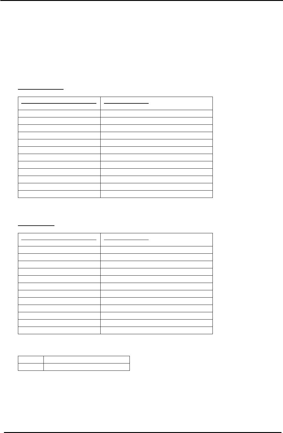
13. The following tables list the Z axis Calibration Data and physical data reference values:
CP-742/743(M)E
Z Axis Calibration Data Item
Reference Value (0.002mm/pulse)
+ Mechanical stopper 24450 +/- 250
+ OT sensor ON (ZL upper + 350) +/- 50
Max Limit Position Z same as the + OT
Loading Position ZL IN 23100 to 23600
Loading Position ZL OUT 23100 to 23600
Middle Loading Position (ZL lower – 14000) +/- 50
Upper Limit Sensor 1 ON (Middle Loading Position – 125) +/- 50
Middle O.T sensor ON (Z0 + 250) +/- 50
Z0 6000 +/- 500
Minimum Limit Position Z same as the – OT
– OT sensor ON – 500 +/- 50
– Mechanical stopper – 1000 +/- 50
CP-732/733E
Z Axis Calibration Data Item
Reference Value (0.002mm/pulse)
+ Mechanical stopper 16850 – 17350
+ OT sensor ON (ZL upper + 300) +/- 50
Max Limit Position Z same as the +OT
Loading Position ZL IN 15500 to 16250
Loading Position ZL OUT 15500 to 16250
Middle Loading Position (ZL lower – 9250) +/- 50
Upper Limit Sensor 1 ON (Middle Loading Position – 125) +/- 50
Middle OT sensor ON (Z0 + 250) +/- 50
Z0 5000 +/- 500
Minimum Limit Position Z same as the – OT
– OT sensor ON – 500 +/- 50
– Mechanical stopper – 1000 +/- 50
<I/O → Servo → IN>
SX019 Z axis + OT (Z plus OT)
SX01A Z axis – OT (Z minus OT)
Fuji Machine Mfg. Co., Ltd. (Okazaki)
SMT Equipment Quality Assurance Dept.
CS Section
3-17