CP7 training(6.0) (1).pdf - 第33页
FK-9F98-27 CP-7 Series T raini ng T ext for Service Engineers Edition 6.0 Chapter 3. X, Y , Z and D-axes Adjustm ent [19/36] 5. Use the adjusting bolt on the claw float cylinder to set the clearance at 0.5mm. Note that t…
FK-9F98-27 CP-7 Series Training Text for Service Engineers
Edition 6.0 Chapter 3. X, Y, Z and D-axes Adjustment [18/36]
3.10 Main Conveyor PCB Clamping Claw Check and Adjustment
3.10.1 (Part 1) Claw Positioning Adjustment
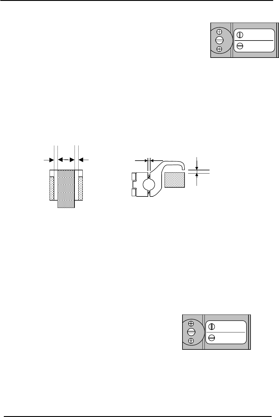
1. Check that the reference pin switch valve is set to “Mark Ref”.
(Not needed for CP-732/733E)
2. Lock the rail-clamping claw at the closed position using the solenoid valve.
Mark Ref.
Pin Ref.
Figure 21
3. Check that all the individual claws are loose.
4. There is some play in the position of the rail-clamping claw center bracket, so check that this is set
at the center of the play.
5. The next step is to lock all the individual claws. When these are locked, the clearance between the
tip of the claw and the guide rail should be in the range of 0.03 to 0.10 mm. (A) Each claw should
be locked using a 4N.m torque wrench. However, before proceeding to lock each claw, there are
some other considerations to bear in mind. (See fig.22)
0.5mm 0.5mm
(A)
0.9 mm
0.03 to 0.10 mm
Figure 22
* Note that 0.5mm clearance on both sides is the ideal. However, this may be difficult to
achieve. In such cases a rough balance between the two is acceptable.
6. Proceed to lock each claw making sure that the clearance values are within the ranges shown
above. It may be useful to lock the two center claws and the two claws at both ends of the rail first,
then proceed to lock the claws in between. Remember that clearance between the tip of the claw
and the guide rail should be in the range 0.03 to 0.10 mm. The claw is attached to the rail by two
3mm bolts. Tightening the top bolt will increase the clearance, tightening the bottom bolt will
decrease the clearance.
3.10.2 (Part 2) Claw Float Adjustment (for CP-742/743(M)E only)
Mark Ref.
Pin Ref.
1. Set the reference pin switch valve to “Pin Ref”.
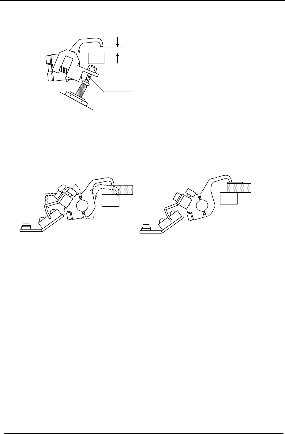
2. Place a 5mm thick PCB in the main conveyor clamper.
3. Activate but do not lock the adjustable rail clamping solenoid.
Figure 23
4. At this position, there should be 0.5mm clearance between the clamper claw tips and the PCB.
Fuji Machine Mfg. Co., Ltd. (Okazaki)
SMT Equipment Quality Assurance Dept.
CS Section
3-18
FK-9F98-27 CP-7 Series Training Text for Service Engineers
Edition 6.0 Chapter 3. X, Y, Z and D-axes Adjustment [19/36]
5. Use the adjusting bolt on the claw float cylinder to set the clearance at 0.5mm. Note that the
clearance will vary slightly at different points on the clamper rail. Set the 0.5mm clearance at the
narrowest point.
Figure 24
5.5mm
Adjustment Bolt
6. On the fixed rail side, set the position of the clamping claw float sensor flag so that the sensor LED
is OFF when a 5mm thick PCB is clamped and ON when a 5.5mm PCB is clamped. Note that the
clamping solenoid should be activated but not locked for this adjustment. I.e. In this case “clamped”
means press the clamping solenoid once but do not lock it. Note: the sensor is Dark-On so when the
LED is OFF the I/O input is ON, and vice versa. I/O: (X05A).
Figure 25
3.10.3 (Part Three) Clamping Cylinder Sensor Adjustment (for all CP7 Series)
1. Check that PCBs in the range of 0.4mm to 5.0mm can be clamped smoothly.
2. There are three clamping cylinders and two sensors on each cylinder. On each cylinder, the upper
sensor is the CLAMP CHECK sensor, and the lower sensor is the UNCLAMP CHECK sensor.
3. For the UNCLAMP CHECK sensors, open the rail to its unclamp limit. At this position find the point
where the sensor LED turns ON then move it 0.5mm further toward the ON direction.
4. Set the CLAMP CHECK sensors so they are ON when a 5.5mm board is clamped and OFF when a
6.5mm board is clamped. Note that the clamping solenoid should be activated but not locked for this
adjustment. I.e. In this case “clamped” means press the clamping solenoid once but do not lock it.
5. Finally confirm that the CLAMP CHECK SENSORS are ON when the clamper rail is clamped with
no PCB in place.
Fuji Machine Mfg. Co., Ltd. (Okazaki)
SMT Equipment Quality Assurance Dept.
CS Section
3-19
FK-9F98-27 CP-7 Series Training Text for Service Engineers
Edition 6.0 Chapter 3. X, Y, Z and D-axes Adjustment [20/36]
6. Clamping Cylinder Sensor locations in the I/O:
<I/0 → Standard →IN>
X05F XY-TABLE PANEL CLAMP CHECK (FIXED RAIL RIGHT)
X060 XY-TABLE PANEL CLAMP CHECK (ADJUSTABLE RAIL RIGHT)
X061 XY-TABLE PANEL UNCLAMP CHECK (FIXED RAIL RIGHT)
X062 XY-TABLE PANEL UNCLAMP CHECK (ADJUSTABLE RAIL RIGHT)
X063 XY-TABLE PANEL CLAMP CHECK (FIXED RAIL LEFT)
IN
X064 XY-TABLE PANEL UNCLAMP CHECK (FIXED RAIL LEFT)
Y043 XY-TABLE PANEL CLAMP (FIXED RAIL)
Y044 XY-TABLE UNPANEL CLAMP (FIXED RAIL)
Y045 XY-TABLE PANEL CLAMP (ADJUSTABLE RAIL)
OUT
Y046 XY-TABLE UNPANEL CLAMP (ADJUSTABLE RAIL)
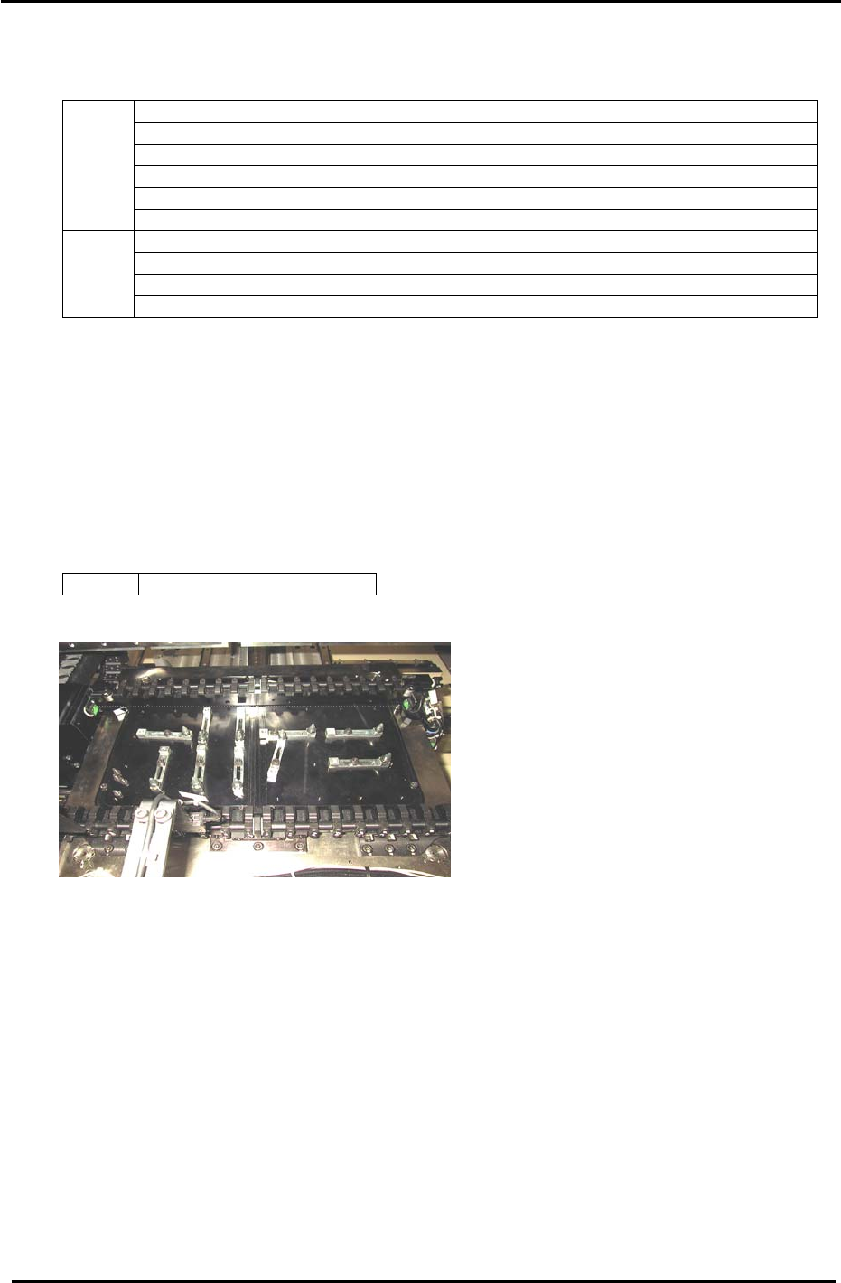
3.11 Back-up Pin Interference Prevention Sensor Adjustment
1. Adjust the bracket and volume pot for the Back-up Pin Interference Prevention sensor so the
sensor reacts when the adjustable rail is within 5mm from the back-up pins and blocks.
2. Check the sensor reaction using the I/O.
<I/0 → Standard → IN>
X07B Back Up Pin Check
Figure 26
Fuji Machine Mfg. Co., Ltd. (Okazaki)
SMT Equipment Quality Assurance Dept.
CS Section
3-20