CP7 training(6.0) (1).pdf - 第34页
FK-9F98-27 CP-7 Series T raini ng T ext for Service Engineers Edition 6.0 Chapter 3. X, Y , Z and D-axes Adjustm ent [20/36] 6. Clamping Cylinder Sensor locations in th e I/O: <I/0 → S tandard → IN> X05F XY -T ABLE…
FK-9F98-27 CP-7 Series Training Text for Service Engineers
Edition 6.0 Chapter 3. X, Y, Z and D-axes Adjustment [19/36]
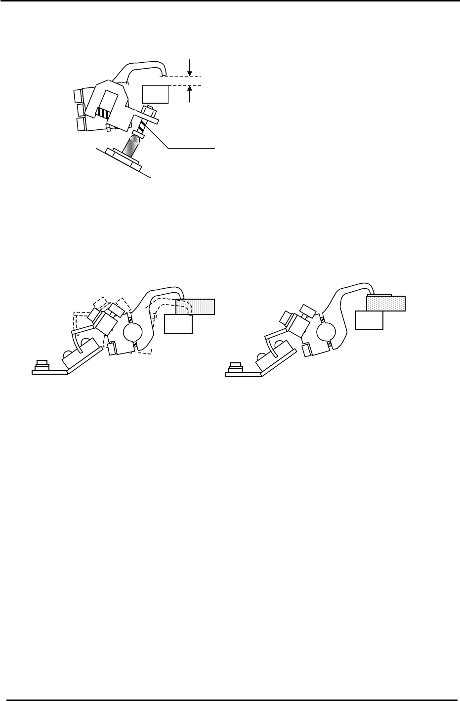
5. Use the adjusting bolt on the claw float cylinder to set the clearance at 0.5mm. Note that the
clearance will vary slightly at different points on the clamper rail. Set the 0.5mm clearance at the
narrowest point.
Figure 24
5.5mm
Adjustment Bolt
6. On the fixed rail side, set the position of the clamping claw float sensor flag so that the sensor LED
is OFF when a 5mm thick PCB is clamped and ON when a 5.5mm PCB is clamped. Note that the
clamping solenoid should be activated but not locked for this adjustment. I.e. In this case “clamped”
means press the clamping solenoid once but do not lock it. Note: the sensor is Dark-On so when the
LED is OFF the I/O input is ON, and vice versa. I/O: (X05A).
Figure 25
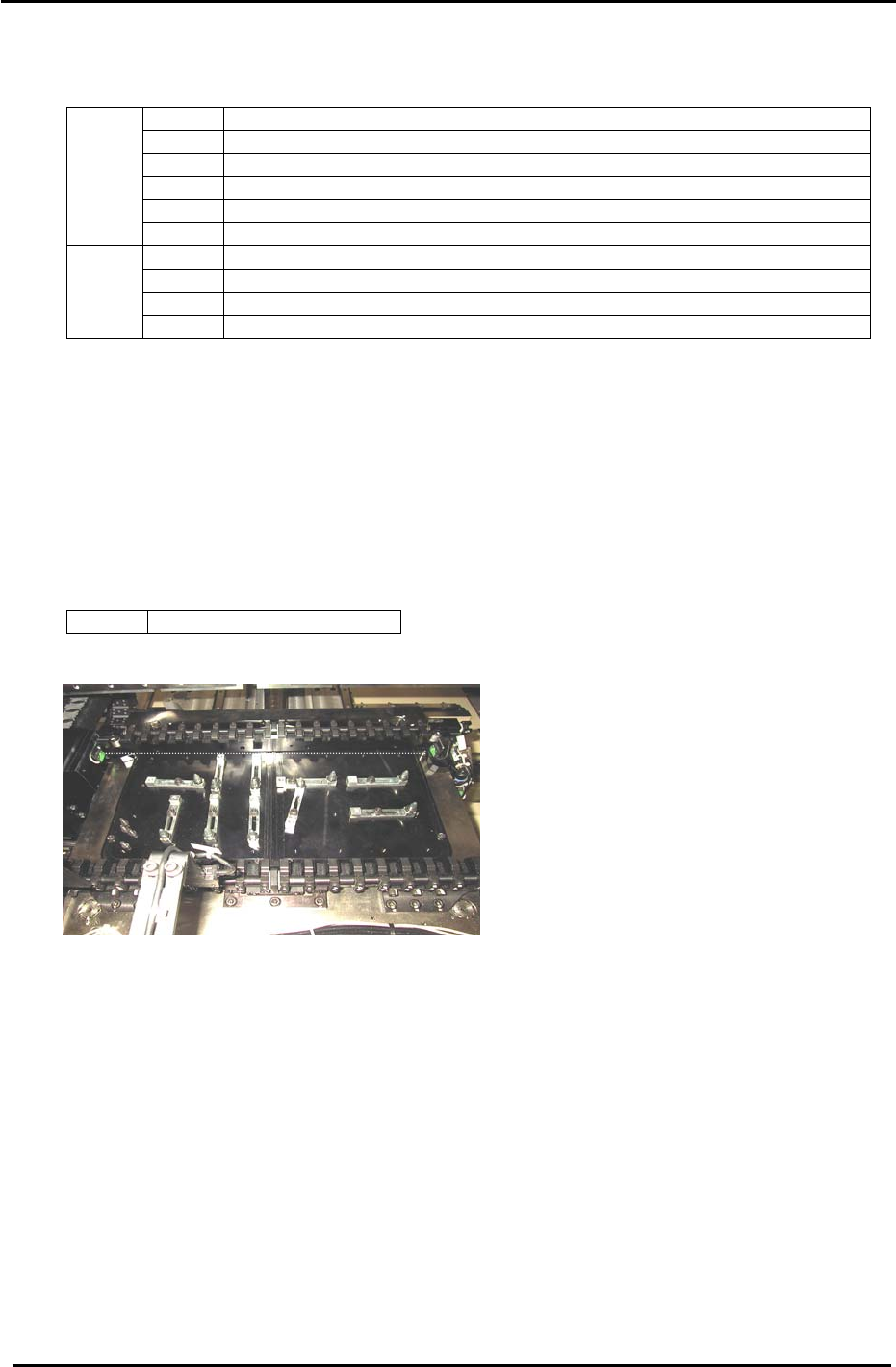
3.10.3 (Part Three) Clamping Cylinder Sensor Adjustment (for all CP7 Series)
1. Check that PCBs in the range of 0.4mm to 5.0mm can be clamped smoothly.
2. There are three clamping cylinders and two sensors on each cylinder. On each cylinder, the upper
sensor is the CLAMP CHECK sensor, and the lower sensor is the UNCLAMP CHECK sensor.
3. For the UNCLAMP CHECK sensors, open the rail to its unclamp limit. At this position find the point
where the sensor LED turns ON then move it 0.5mm further toward the ON direction.
4. Set the CLAMP CHECK sensors so they are ON when a 5.5mm board is clamped and OFF when a
6.5mm board is clamped. Note that the clamping solenoid should be activated but not locked for this
adjustment. I.e. In this case “clamped” means press the clamping solenoid once but do not lock it.
5. Finally confirm that the CLAMP CHECK SENSORS are ON when the clamper rail is clamped with
no PCB in place.
Fuji Machine Mfg. Co., Ltd. (Okazaki)
SMT Equipment Quality Assurance Dept.
CS Section
3-19
FK-9F98-27 CP-7 Series Training Text for Service Engineers
Edition 6.0 Chapter 3. X, Y, Z and D-axes Adjustment [20/36]
6. Clamping Cylinder Sensor locations in the I/O:
<I/0 → Standard →IN>
X05F XY-TABLE PANEL CLAMP CHECK (FIXED RAIL RIGHT)
X060 XY-TABLE PANEL CLAMP CHECK (ADJUSTABLE RAIL RIGHT)
X061 XY-TABLE PANEL UNCLAMP CHECK (FIXED RAIL RIGHT)
X062 XY-TABLE PANEL UNCLAMP CHECK (ADJUSTABLE RAIL RIGHT)
X063 XY-TABLE PANEL CLAMP CHECK (FIXED RAIL LEFT)
IN
X064 XY-TABLE PANEL UNCLAMP CHECK (FIXED RAIL LEFT)
Y043 XY-TABLE PANEL CLAMP (FIXED RAIL)
Y044 XY-TABLE UNPANEL CLAMP (FIXED RAIL)
Y045 XY-TABLE PANEL CLAMP (ADJUSTABLE RAIL)
OUT
Y046 XY-TABLE UNPANEL CLAMP (ADJUSTABLE RAIL)
3.11 Back-up Pin Interference Prevention Sensor Adjustment
1. Adjust the bracket and volume pot for the Back-up Pin Interference Prevention sensor so the
sensor reacts when the adjustable rail is within 5mm from the back-up pins and blocks.
2. Check the sensor reaction using the I/O.
<I/0 → Standard → IN>
X07B Back Up Pin Check
Figure 26
Fuji Machine Mfg. Co., Ltd. (Okazaki)
SMT Equipment Quality Assurance Dept.
CS Section
3-20
FK-9F98-27 CP-7 Series Training Text for Service Engineers
Edition 6.0 Chapter 3. X, Y, Z and D-axes Adjustment [21/36]
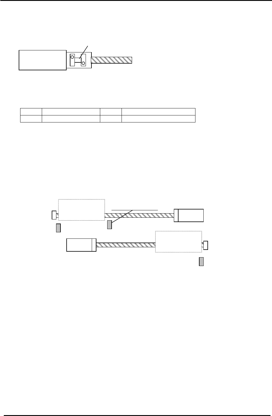
3.12 D-axis Adjustment and Calibration Data Setting
3.12.1 D-axis Adjustment and Calibration Data setting for CP-742/743(M)E and CP-732/733E
Coupling
MOTOR
Figure 27
1. Use the I/O to set the D1 and D2 tables as follows:
<I/0 → Standard → OUT>
Y057 D1 PALLET DOWN Y059 D1 STOPPER UNCLAMP
Y067 D2 PALLET DOWN Y069 D2 STOPPER UNCLAMP
2. To allow access to the D1 coupling, manually move the D2 table towards the center of the D-axis.
3. Check that the coupling is free to move and is centered between the motor and ball screw shafts.
Note: Be careful when handling the coupling as some edges may be sharp!
4. Remove the minus OT brackets for D1 and D2.
D1 Motor
D2 Motor
D2 Pallet
− Stopper
+ Stopper
D1 Pallet
−
Stopper
Interference Prevention
Sensor
D1 + OT (SX041)
D2 + OT (SX049)
D1
− OT Sensor
(SX042)
+ Stopper
D2 − OT Sensor
(SX04A)
Figure 28
5. Manually turn the ball screw and set the D1 pulse count to 5000 pulses. (D2: Minus 5000)
6. Pull D1 against the + mechanical stopper. (D2 against the
− mechanical stopper)
7. Half lock the two visible coupling bolts, one on each side of the coupling.
8. Move D1/D2 away from their mechanical stoppers.
9. Lock the four 5mm bolts in rotation with an 8.3N.m torque wrench (CP-742/743(M)E).
For CP-732/733E, use an 8.3N.m torque wrench for the 4mm bolts and a 4N.m torque wrench for
the 3mm bolts.
Be careful to ensure that the coupling is locked equally at all 4 points, i.e. the gaps in the coupling
should be roughly equal.
10. Set the
− OT (D1 / D2) sensors 3500 pulses back from their respective mechanical stoppers.
Check that the OT sensor flag is in the center of the sensor.
Fuji Machine Mfg. Co., Ltd. (Okazaki)
SMT Equipment Quality Assurance Dept.
CS Section
3-21