CP7 training(6.0) (1).pdf - 第44页
FK-9F98-27 CP-7 Series T raini ng T ext for Service Engineers Edition 6.0 Chapter 3. X, Y , Z and D-axes Adjustm ent [30/36] 3.13 D-axis Pallet Flatness Measurement 1. Flatness of the top plates on the pallet s is import…
FK-9F98-27 CP-7 Series Training Text for Service Engineers
Edition 6.0 Chapter 3. X, Y, Z and D-axes Adjustment [29/36]
**Apply AFC grease to the locations hi-lighted (Fig. 39) on the D-table base.
17. Apply Daphne Eponex #2 to the four D-table springs.
1 2
3 4
(1) lower sensor
(3) upper sensor
(4) notch stopper
bracket
(5) stopper sensors
Figure 39
(2)
Figure 40
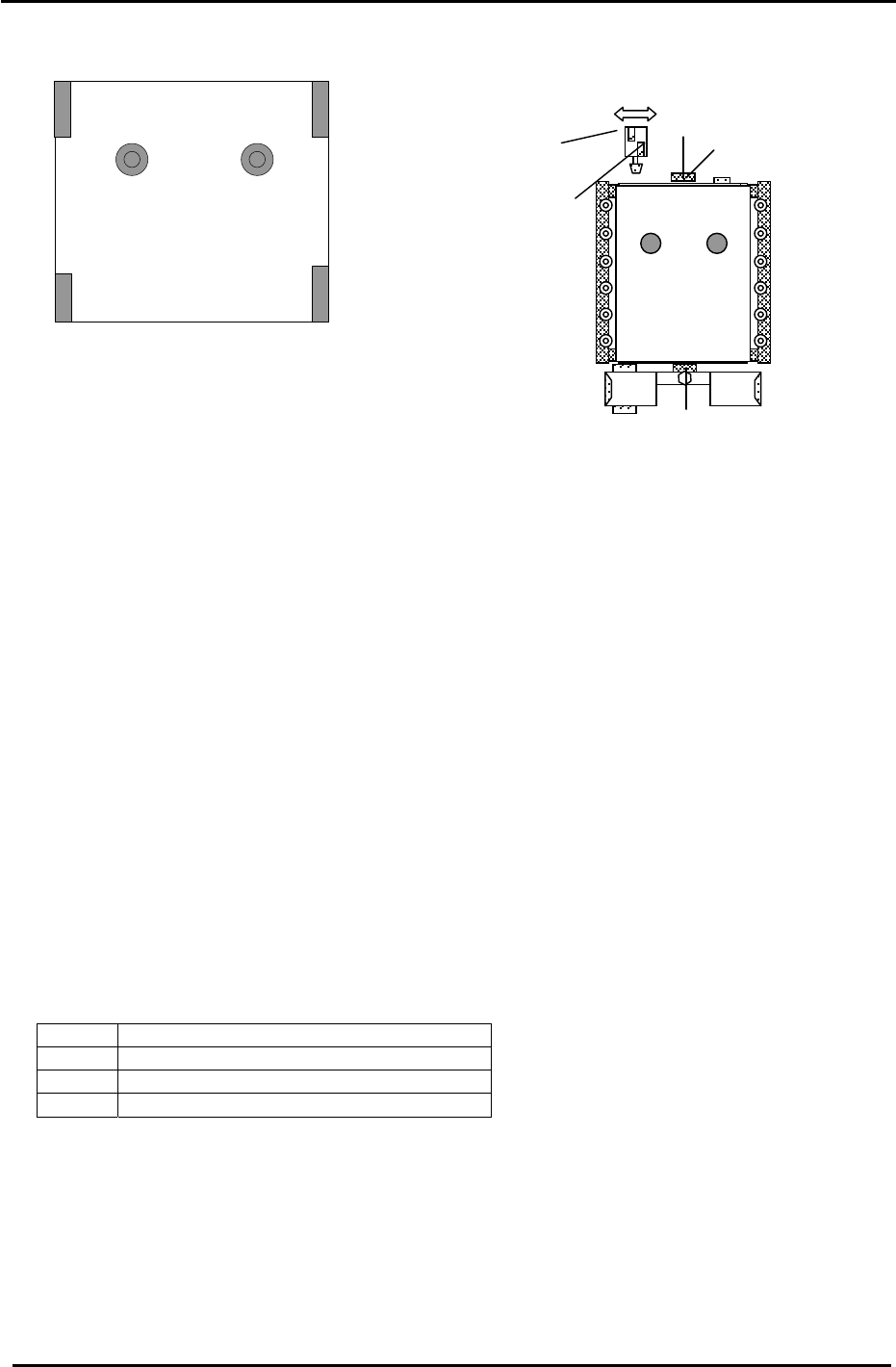
18. Replace the pallet.
19. Adjust the pallet sensors (1 at upper limit, 2 at lower limit) mounting bracket in the forward/back
directions until the gap between the sensor and dog surface is 1mm.
20. Place two 0.6mm spacers at positions 1 and 2 shown in fig. 39. (CP732/733 ONLY)
21. Lower the table.
22. Set the front side PALLET SETTING CHECK (2) sensor so that it turns OFF with the 0.6mm
spacers in place and ON with 0.4mm spacers in place. I/0: D1 (X088), D2 (X09E) (CP732/733
ONLY)
23. Place 0.6mm spacers at positions 3 and 4 shown in fig. 39, then set the back PALLET SETTING
CHECK (1) sensor so that it turns OFF with the 0.6mm spacers in place and ON with 0.4mm
spacers in place. I/O: D1 (X087), D2 (X09D).
24. Remember to check the PALLET ARRIVE CHECK sensor (3). Check that it is ON when the D-
table is at the upper limit. I/O: D1 (X086), D2 (X09C)
25. For the D-axis notch stopper adjustment (4), Make sure the D pulse count is zero pulses. Move the
stopper bracket so the piston aligns with the center of the notch in the D- table.
26. Set the TABLE STOPPER LOCK CHECK and UNLOCK CHECK sensors (5) 0.5mm toward the
position they turn ON.
<I/O → Standard → IN>
X080 D1 TABLE STOPPER LOCK CHECK
X081 D1 TABLE STOPPER UNLOCK CHECK
X096 D2 TABLE STOPPER LOCK CHECK
X097 D2 TABLE STOPPER UNLOCK CHECK
Fuji Machine Mfg. Co., Ltd. (Okazaki)
SMT Equipment Quality Assurance Dept.
CS Section
3-29
FK-9F98-27 CP-7 Series Training Text for Service Engineers
Edition 6.0 Chapter 3. X, Y, Z and D-axes Adjustment [30/36]
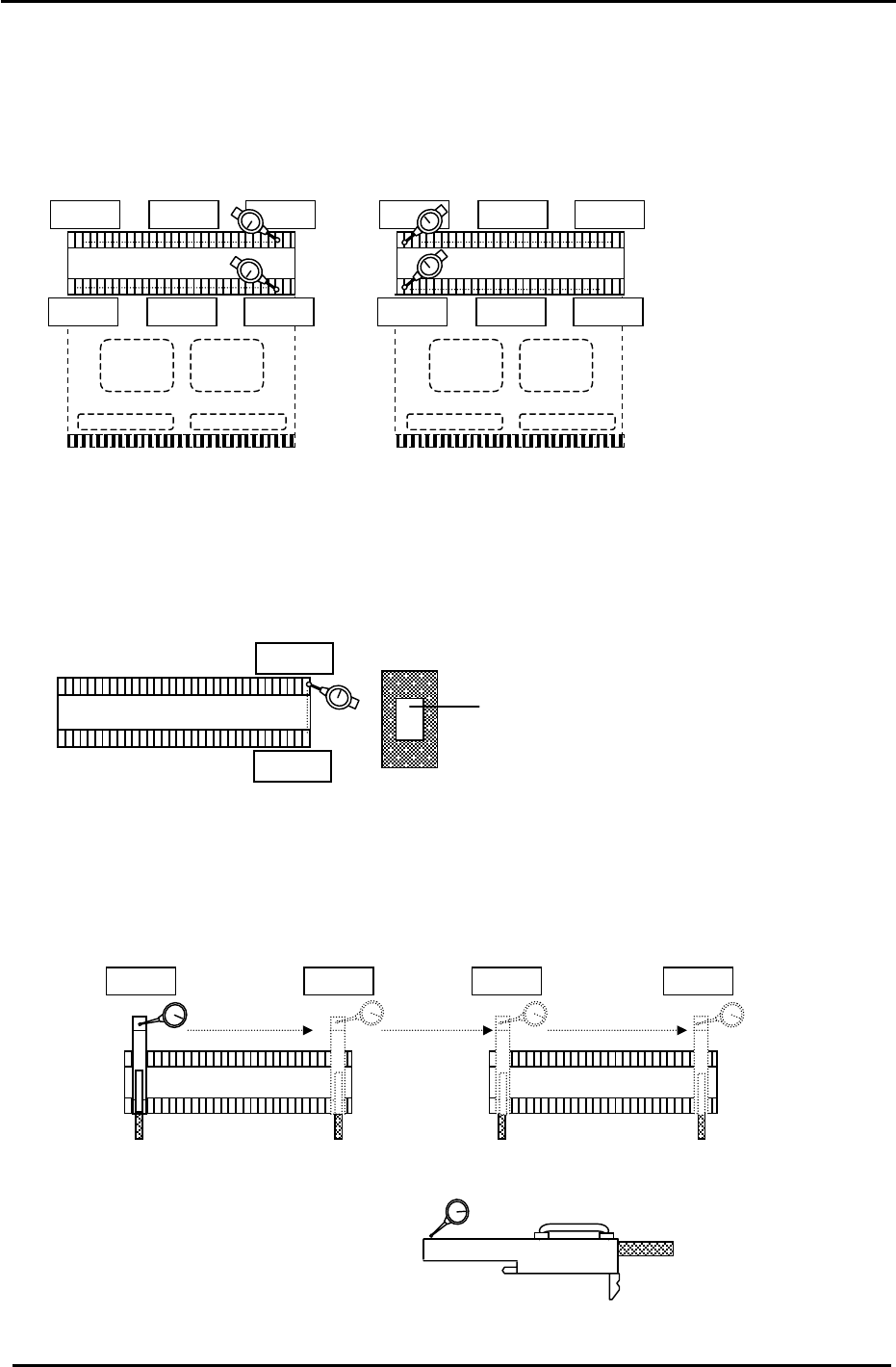
3.13 D-axis Pallet Flatness Measurement
1. Flatness of the top plates on the pallets is important to maintain consistent pick up. Set up two dial
gauges as pictured and indicate the top surface of the feeder plate at the positions illustrated in
Fig.41. (Tolerance: within 0.10mm)
0
D2Pallet
D1Pallet
0
0
Figure 41
2. If the flatness measurement is out of tolerance, ensure that there are no components caught
between the D-axis base plate and pallet. (if problems persist, replace the pallet)
3. Set a dial gauge and block on the machine base and check the flatness from A to B.
(Tolerance: within 0.05mm)
D1 Pallet
0
A
Dial Gauge Block
Jig No.: DCPJ0750
Figure 42
4. Install the feeder height jig at the second and next to last feeder slots on each pallet. Check the
flatness of the D1 and D2 pallets. (4 points in total) (Tolerance: within 0.05mm)
Feeder Height Jig
Jig No.: Z5413AWPJ9270
Figure 43
D1 Pallet
0
D2 Pallet
Fuji Machine Mfg. Co., Ltd. (Okazaki)
SMT Equipment Quality Assurance Dept.
CS Section
3-30
FK-9F98-27 CP-7 Series Training Text for Service Engineers
Edition 6.0 Chapter 3. X, Y, Z and D-axes Adjustment [31/36]
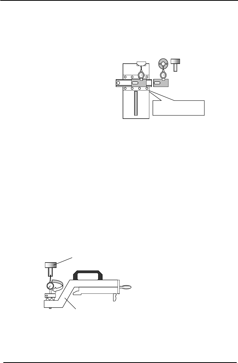
3.14 Cam Box Positioning Check
1. Attach the positioning jig onto the “A” shaft. Set the cam at 0 and turn the Pick-up valve ON. (Y031)
2. Position the A shaft at station 1 and set the cam to 170 degrees.
3. Install the cam box alignment jig on the pallet.
0 to 0.05mm
(Tolerance: 0 to + 0.05mm)
Do not inch with the jig
attached to the
p
allet.
JIG A
Cam box alignment
Jig No.: ADCPJ8271
(Jig No.:ADCPJ8130)
4. Check the cam box position at slots:
3 & 28 of D1 & D2 (CP-732/733E)
3 & 38 of D1 & D2 (CP-742ME)
3 & 68 of D1 & D2 (CP-742E)
Figure 44
3.15 Pick-up Position Calibration
1. Attach the positioning jig onto the A Shaft.
(Jig No.:ADCPJ8130)
2. Set the “Pick up Position” jig on the D1/D2 table at slot No.1. (Jig No.:ADCCPJ8251)
3. Turn the Pick-up valve ON (Y031) and set the cam to 170 degrees at Sta. 1.
4. Balance the dial gauge on both sides of the positioning jig in the X-direction.
When the gauge is balanced on each side, this becomes pick up position D1/D2.
Press: [Maintenance] → [Calibration] → [Pick Up Reference] → [D1/D2] → [Set]
(Jig No.:ADCPJ8130)
“Pick up pos” jig
(Jig No.:ADCCPJ8251)
Figure 45
Fuji Machine Mfg. Co., Ltd. (Okazaki)
SMT Equipment Quality Assurance Dept.
CS Section
3-31