CP7 training(6.0) (1).pdf - 第50页
FK-9F98-27 CP-7 Series T raini ng T ext for Service Engineers Edition 6.0 Chapter 4. S tation Adjustment [1/28] Chapter 4 S t ation Adjustment 4.1 Shaft Assembly Adjustment 1. With the cam at 0 degrees, turn the 9 th sta…
FK-9F98-27 CP-7 Series Training Text for Service Engineers
Edition 6.0 Chapter 3. X, Y, Z and D-axes Adjustment [35/36]
3.19 Placing Height Z0 Calibration
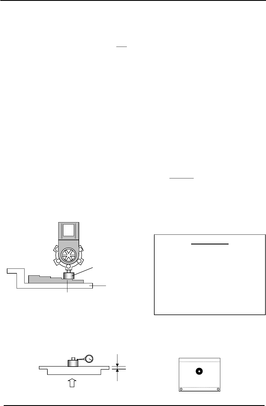
Carry out the procedure listed below to set the Placing Origin height. (Z0)
NOTE: Calibrate only after adjusting the ST9
slider height.
1. Turn the ST9 solenoid valve ON at 0 degrees.
Y035 PLACE SOL ENGAGED
2. After the Z- axis adjustment is completed, clamp the jig plate (fig. 53) in the middle of the table,
and install the nozzle jig in the A holder.
3. Manually move the jig under the ST9, placing point.
4. Set the cam angle at 195 degrees to lower the nozzle jig. Manually raise the Z-axis so that the
nozzle jig is in contact with a feeler gauge jig (-0.3mm). The Z-axis servo counter at this time is
Z0.
Target: CP-732/733E (5000 +/-500 pulses)
Target: CP-742/743(M)E (6000 +/-500 pulses)
5. Calibrate “Z0” on the reference side, adjustable side and center of the jig plate. The
deviation between each measuring point should be within 50 pulses
of each other.
6. Enter the average value (of the three measurement points) to the Calibration Data as
follows:
Press: [Maintenance] → [Calibration] → [Placing Reference] → [Z0] → [Set]
Nozzle Jig No.:DCPJ0620
A
IMPORTANT!!
The placing height calibration is critically
important to ensuring stable placement.
If not adjusted correctly, damage to
components may occur (due to shock
from nozzle) or placing accuracy will not
be at optimum levels. Be sure to use
care when making adjustments in this
area.
Jig No.: AWPJ8111
-0.3mm
Figure 53
7. Alternatively, clamp the XC/YC calibration plate in the center of the table. Raise the Z-axis until
the dial gauge deflects 0.3mm. The Calibration Data value will be the servo pulse count with the
gauge deflected 0.3, plus 1050 (thickness of the jig plate). This procedure works well resulting
in basically the same value as obtained using the procedure in steps 1 to 6.
2.1mm
2.1/ 0.002 = 1050
0.3mm
Jig No.: AJPJ0062
Figure 54
Fuji Machine Mfg. Co., Ltd. (Okazaki)
SMT Equipment Quality Assurance Dept.
CS Section
3-35
FK-9F98-27 CP-7 Series Training Text for Service Engineers
Edition 6.0 Chapter 4. Station Adjustment [1/28]
Chapter 4 Station Adjustment
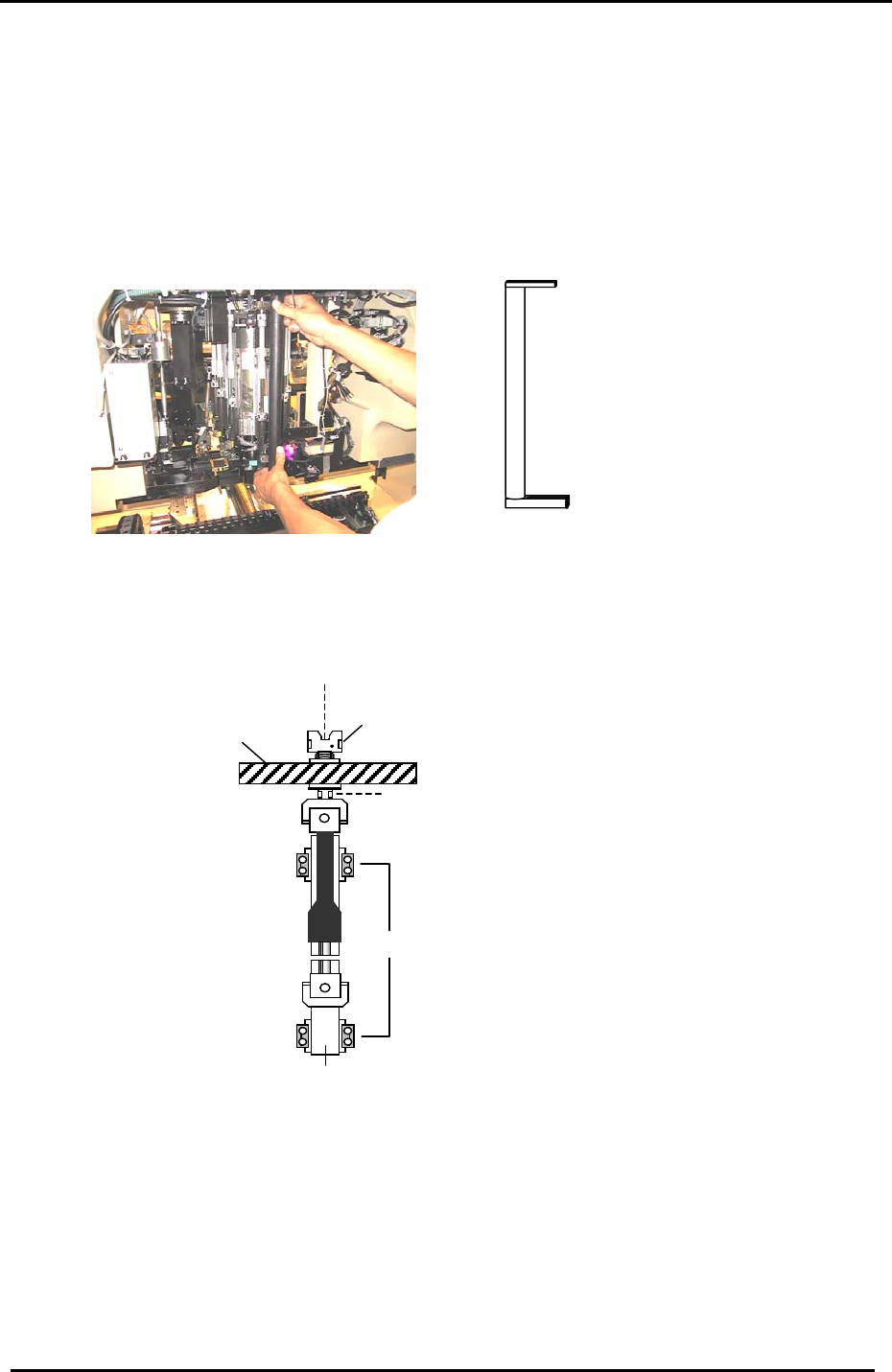
4.1 Shaft Assembly Adjustment
1. With the cam at 0 degrees, turn the 9
th
station placing solenoid valve OFF. (Y034)
2. Make sure that there is a nozzle holder on shaft A.
3. Check the alignment of the holder and clutch at 195 degrees. Use the jig indicated in
Fig.1.
Jig No. CP-732/733E: DCPJ0431
CP-742/743(M)E: DGPJ0020.
Figure 1
4. If the holder and clutch are not aligned correctly, use a 7mm spanner at position A in the
diagram below; and a 2.5mm L-wrench at position B, to loosen the shaft assembly and realign
them.
LM guide block retainers
A
Helical gear
Clutch
Linear guide rail
Figure 2
B
5. When the clutch and holder on the shaft assembly are correctly aligned, there should be no
resistance with the jig.
6. Finally, in preparation for the adjustments that follow, remove the holder from shaft A.
Fuji Machine Mfg. Co., Ltd. (Okazaki)
SMT Equipment Quality Assurance Dept.
CS Section
4-1
FK-9F98-27 CP-7 Series Training Text for Service Engineers
Edition 6.0 Chapter 4. Station Adjustment [2/28]
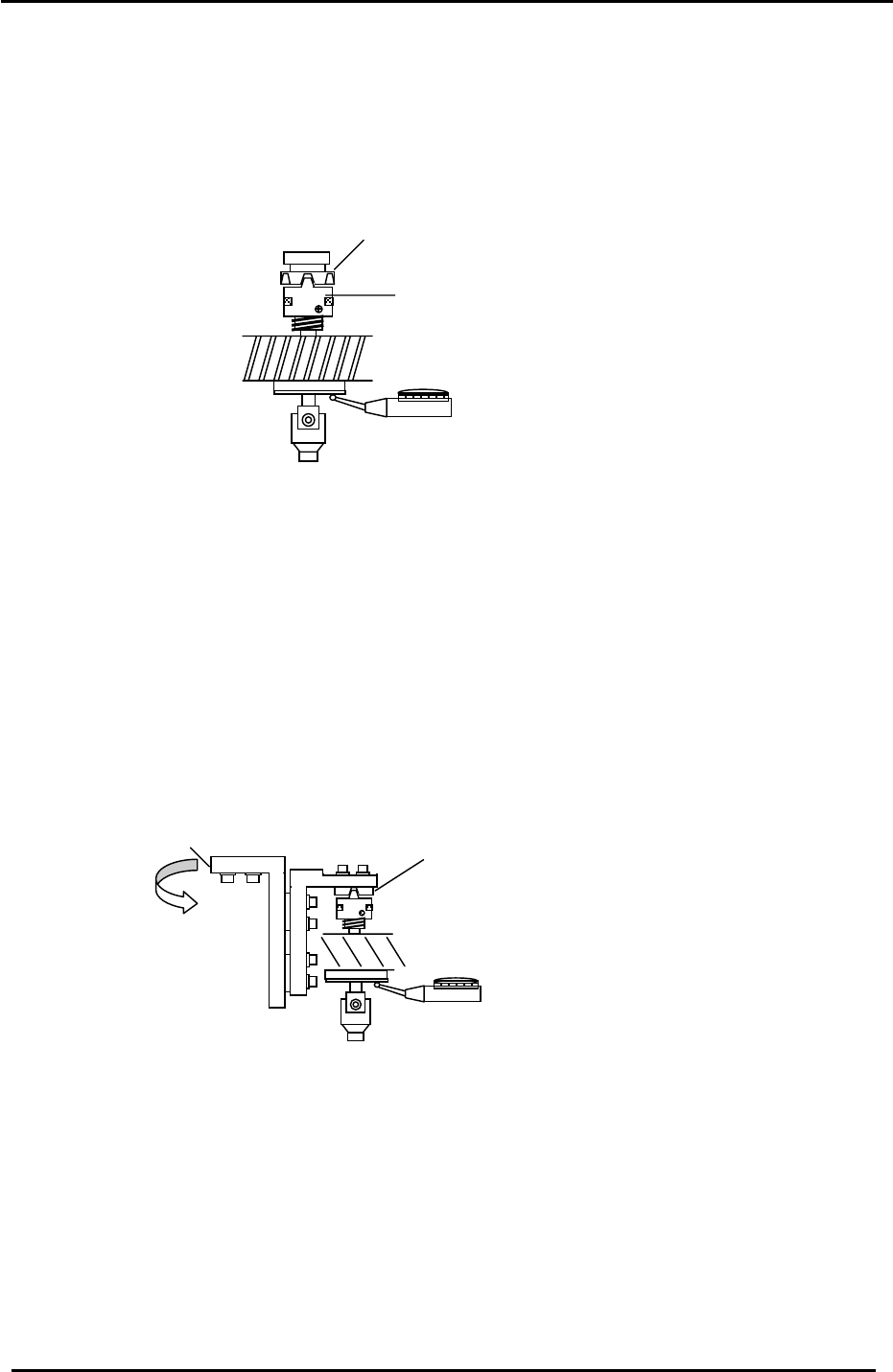
4.2 PQ, FQ, and RQ Stroke Adjustment
1. Adjustments should be performed with the servo power OFF.
2. Use the low shaft (identified in section 3.16) to set the stroke of stations 2, 8, and 10.
3. With the cam at 200 degrees, clutch (1), and the low shaft clutch (2) should be engaged.
Figure 3
1
2
4. Set the stroke in the range of 0.30 to 0.35mm, (0.31mm is the ideal value). Note that the
stroke value will change when rotating the shaft; set the stroke at the point where the shaft
descends the least. When rotating the shaft, the stroke should not fluctuate by more than
0.05mm.
4.3 3
rd
Station Origin Position and Stroke Adjustment
1. This adjustment should be performed with the servo power OFF.
2. Move the low shaft to the 3
rd
station at 200 degrees.
3. Engage and align the 3
rd
station clutch (1) with the low shaft, by adjusting the position of
bracket (2):
2
1
Figure 4
4. To check that the clutch and low shaft are properly aligned, rotate the shaft, and measure the
difference in stroke when the shaft is at 0, 90, 180, and 270 degrees. Tolerance is 0.030mm.
5. Once the clutch is aligned within tolerance, proceed to set the 3
rd
station stroke.
Fuji Machine Mfg. Co., Ltd. (Okazaki)
SMT Equipment Quality Assurance Dept.
CS Section
4-2