CP7 training(6.0) (1).pdf - 第57页
FK-9F98-27 CP-7 Series T raini ng T ext for Service Engineers Edition 6.0 Chapter 4. S tation Adjustment [8/28] 4.8 10 th St ation Clutch Engagement Check Sensor 1. Set the clearance between the fiber sens or and the mes…
FK-9F98-27 CP-7 Series Training Text for Service Engineers
Edition 6.0 Chapter 4. Station Adjustment [7/28]
6. Set the sensor amp to D-ON.
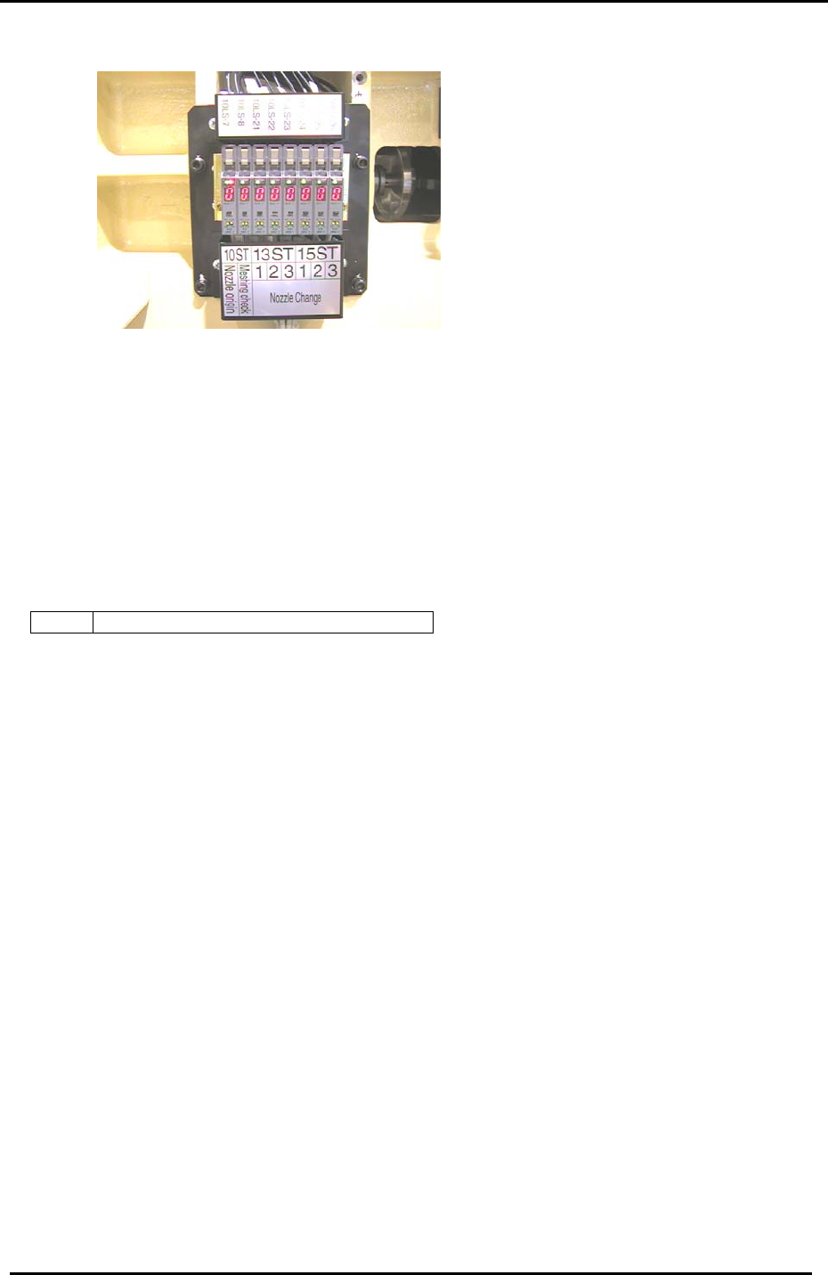
Figure 12
7. Set the mode switch to SET.
8. Press the tuning button once when the beam is in the center of the nozzle origin hole.
9. Rotate the shaft until the beam is away from the hole and focused on the clutch itself. Press the
tuning button one more time and set the mode switch to run.
10. Check to confirm that the amplifier reads 0 when the beam is focused on the center of the hole
and 9 when focused elsewhere on the clutch.
11. Confirm sensor operation using the I/O:
<I/O → Standard → IN>
X039 ST10 NOZZLE CLUTCH ORIGIN POS.
Fuji Machine Mfg. Co., Ltd. (Okazaki)
SMT Equipment Quality Assurance Dept.
CS Section
4-7
FK-9F98-27 CP-7 Series Training Text for Service Engineers
Edition 6.0 Chapter 4. Station Adjustment [8/28]
4.8 10
th
Station Clutch Engagement Check Sensor
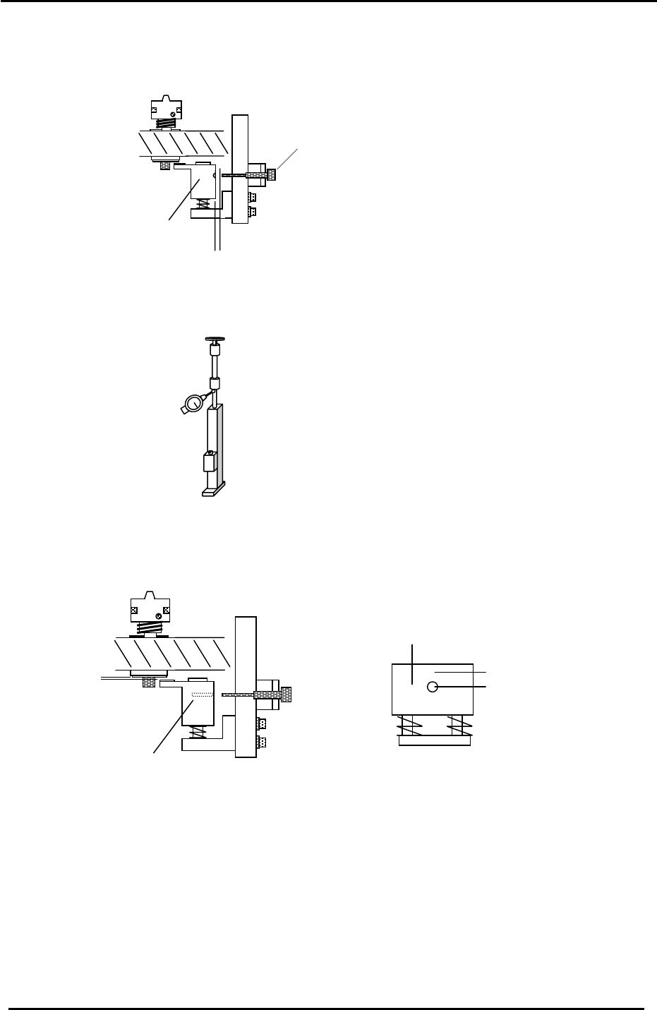
1. Set the clearance between the fiber sensor and the meshing check block to 1mm.
2. Set a dial gauge on the low-shaft as illustrated in the diagram below:
Meshing Check Block
Meshing Check Sensor
1mm
Figure 13
3. Set the clearance between the clutch underside (when it is properly engaged) and the meshing
check block to 0.2mm by adjusting bolts “A” shown in figure 14. Measure the clearance by
depressing the shaft until you feel it make contact with the meshing check block.
Meshing Check Block
“A”
Figure 14
0.2mm
Meshing Check Block
A
mplifier displays 9 here
A
mplifier displays 0 here
4. Adjust the fiber sensor bracket so that the sensor aligns with the through hole in the meshing
check block.
5. Set the sensor amplifier to L-ON and set the mode switch to SET.
6. Make sure the shaft is correctly engaged, then press the tuning button once; (at this point the
beam is centered in the hole).
7. Disengage the shaft from the 10
th
station clutch so that the top of the shaft and the station clutch
are not aligned. Press the tuning button one more time; (at this point the beam is focused above
the hole).
Fuji Machine Mfg. Co., Ltd. (Okazaki)
SMT Equipment Quality Assurance Dept.
CS Section
4-8

FK-9F98-27 CP-7 Series Training Text for Service Engineers
Edition 6.0 Chapter 4. Station Adjustment [9/28]
8. Set the amplifier mode switch to RUN.
9. Confirm for all shafts that the amplifier display reads 0 when the clutch is correctly engaged at 200
degrees, and 9 when the clutch is NOT correctly engaged.
Note: In some cases, it may be necessary to keep re-tuning the sensor amplifier until you get
results of 0 and 9 for all shafts. If these results cannot be achieved, the clearance between
the clutch underside and the meshing check block may not be enough, or the optical fiber
connections to the amplifier may need trimming with a fiber cutter.
10. Confirm sensor operation using the I/O:
<I/O → Standard → IN>
X03A ST10 NOZZLE CLUTCH ENGAGEMENT CHECK
Fuji Machine Mfg. Co., Ltd. (Okazaki)
SMT Equipment Quality Assurance Dept.
CS Section
4-9