CP7 training(6.0) (1).pdf - 第61页
FK-9F98-27 CP-7 Series T raini ng T ext for Service Engineers Edition 6.0 Chapter 4. S tation Adjustment [12/28] Figure 19 6. T o check the stroke, the cam needs to be set at a specific angle. Due to rece nt changes of t…
FK-9F98-27 CP-7 Series Training Text for Service Engineers
Edition 6.0 Chapter 4. Station Adjustment [11/28]
7. Confirm that the N.C intersection lever shown in figure 15 (item 6) is horizontal when the cam is at
0 degrees. Adjust otherwise.
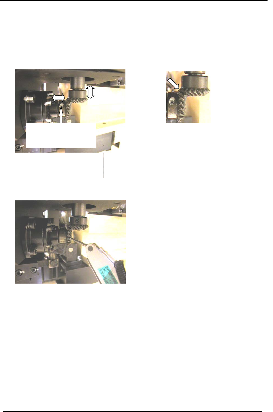
4.9.2 Nozzle Changer Gear Backlash Adjustment
1. Confirm that the two gears where the motor intersects the NC axis are aligned correctly. Then,
lock the 4 small set screws (there are two on each gear):
One of 2 set screws on each
bevel gear. (Ensure the
screws are seated at the
flats on each shaft.
)
Figure 17
2. Turn the servo ON.
3. Place a dial gauge on the lower of the two gears (figure 18) and measure the backlash of the gear
at four points: 0, 90, 180 and 270 degrees. The backlash should be in the range 0.03 to 0.13mm.
If the backlash is not in range, realign the two gears as described in step 1.
Figure 18
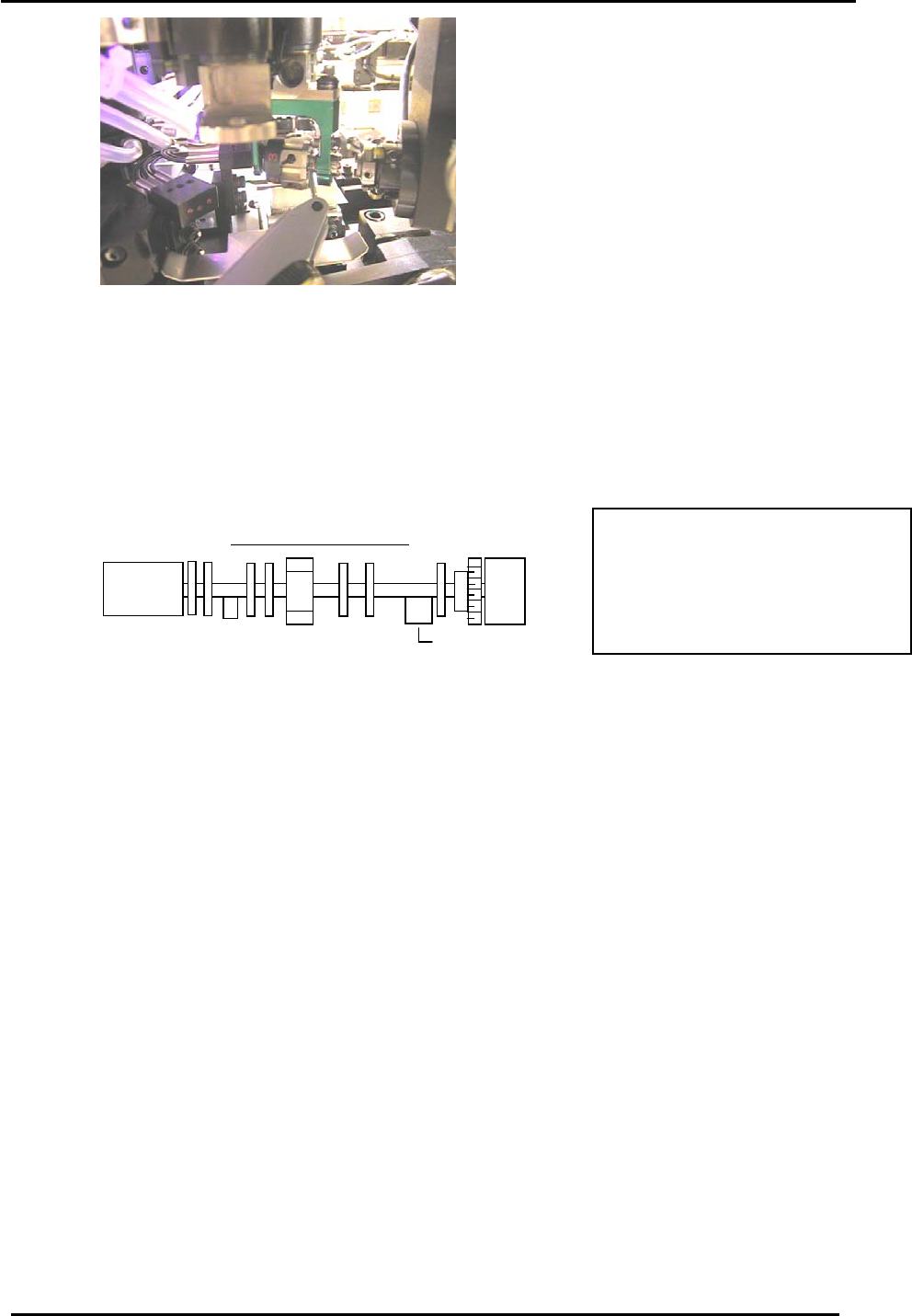
4.9.3 Nozzle Changer Stroke Adjustment
1. Turn the servo OFF and attach a nozzle holder to shaft A.
2. Set the 10
th
station RQ to its original position and rotate the A-shaft through the 10
th
station to
make sure the nozzle holder is aligned correctly.
3. Rotate the “A “ shaft with holder attached to the 13
th
station at 0 degrees.
4. Turn ON the 14
th
station, nozzle changer solenoid valve by I/O: [I/O] → [Standard] →
[OUT] → Y037 ST14 NOZ CHANGE SOLENOID ENGAGED.
5. Rotate the A-shaft towards the 14
th
station and just before the nozzle changer clutch engages with
the nozzle holder (at around 130 degrees) place a dial gauge on the nozzle holder as shown in
figure 19 on the following page.
Fuji Machine Mfg. Co., Ltd. (Okazaki)
SMT Equipment Quality Assurance Dept.
CS Section
4-11
FK-9F98-27 CP-7 Series Training Text for Service Engineers
Edition 6.0 Chapter 4. Station Adjustment [12/28]
Figure 19
6. To check the stroke, the cam needs to be set at a specific angle. Due to recent changes of the B-
cam assembly, the cam angle depends on the type of B-cam assembly. To identify which type,
look at the markings on the side of the B-axis counter balance lobe.
If the marking is “3 or 4”, the cam angle should be set to 141 degrees and the stroke amount
should be within 0.01 to 0.05mm. (“3 or 4” identifies the old type B-axis assembly)
If the marking is “x”, the cam angle should be 146 degrees and the stroke amount should be
within 0.01 to 0.05mm. (“X” indicates the newer type B-axis assembly)
B -axis cam assembly
4
Counter balance
CP742(M)E/732E = 141 degrees
CP743(M)E/733E = 146 degrees
Or
Check the marking on the B-cam
as indicated in step 6.
7. If not within range, loosen the two bolts of the stroke adjustment rod (item 1 in figure 15) and turn
the rod to change the stroke amount.
8. Once the stroke is set within range, lock the two bolts and recheck the stroke.
4.9.4 Nozzle Change Origin Position Calibration
1. Set a shaft at the RQ origin position and move it to station 13 at 0 degrees. (This action will align
the nozzle holder to the correct position for nozzle changing)
2. Rotate the NC motor to around zero pulses. Rotate the rotor until it is horizontal. When the rotor
is horizontal, the pulse count must be within 0 +/- 1800.
3. Turn the 14
th
Station solenoid valve ON. (Y037) and slowly rotate the cam to 141 degrees
(CP742(M)E/732E) or 146 degrees (CP743(M)E/733E) to engage the NC clutch rotor with the
nozzle holder clutch at station 14 while holding the clutch horizontal.
4. Move the cam-axis to a position where the clutch starts to engage and where the backlash
decreases for the NC clutch rotation.
5. When the lower gear is rotated in the above situation, the counter will vary due to the backlash.
Take the center value and set it as the NC Origin Position.
Note: The Calibration Data can be either plus or minus. However, make sure that the value does
not exceed +/- 1800 pulses.
Press: [Maintenance] → [Calibration] → [Origin Position Offset] → [NC]
Fuji Machine Mfg. Co., Ltd. (Okazaki)
SMT Equipment Quality Assurance Dept.
CS Section
4-12
FK-9F98-27 CP-7 Series Training Text for Service Engineers
Edition 6.0 Chapter 4. Station Adjustment [13/28]
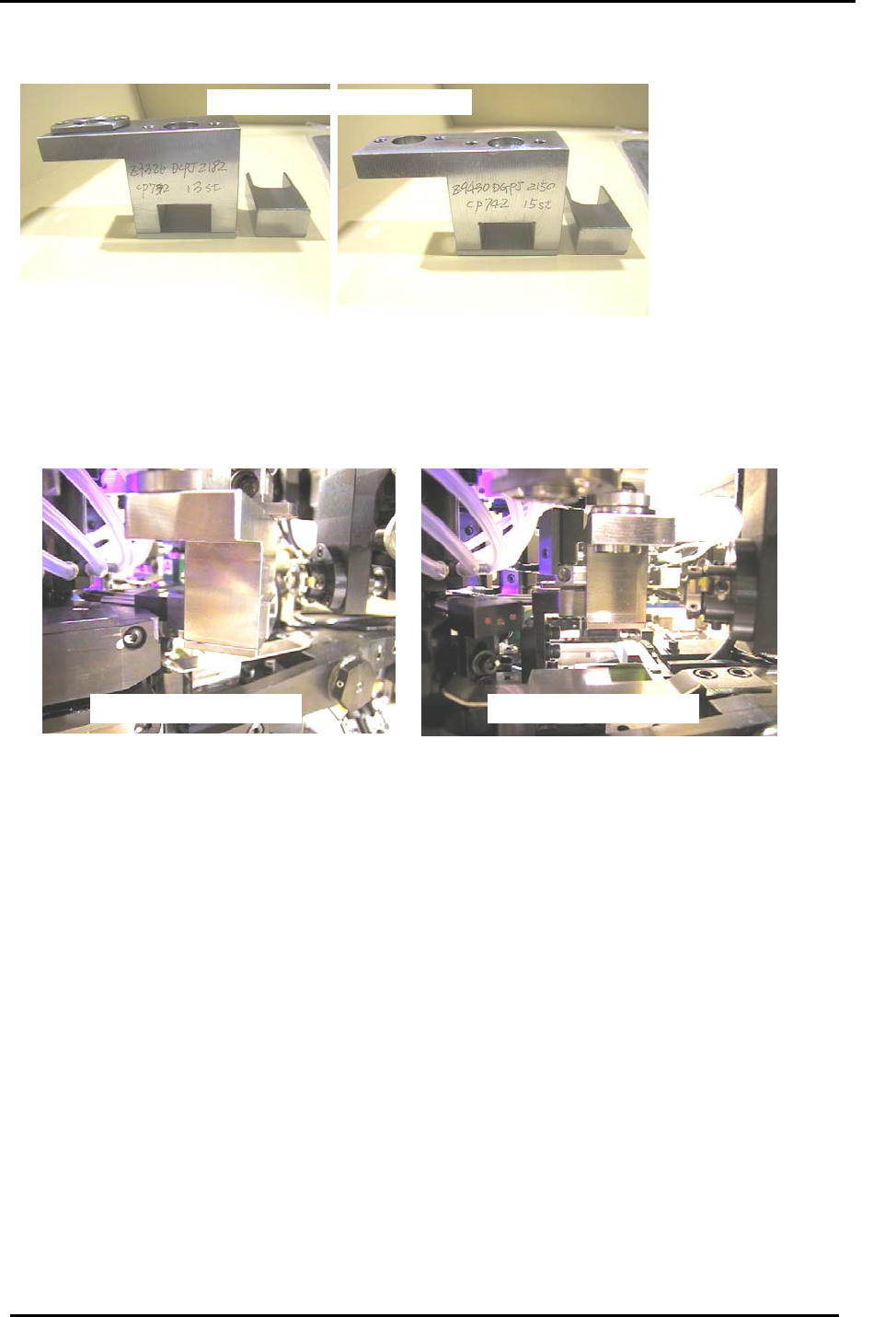
4.10 Nozzle Type Check Sensor Adjustment at the 13
th
and 15
th
Stations
13
TH
Station sensor alignment jig
13 station and 15 station JIG SET
15
TH
Station sensor alignment jig
Figure 20
CP-732/733E Jig No.
A
DGPJ8030
CP-742/743(M)E Jig No.
A
DCPJ8050
1. Remove the 13
th
station reject parts brush, as this will interfere with the jigs.
2. Move the cam to 200 degrees. Install the above jigs in turn and check/adjust the alignment of
the 13
th
and 15
th
stations by sliding the “sliding jig” into the sensor holder brackets.
Caution – the jigs span two shafts so never rotate the cam when they are in place.
Station 13 sensor ali
g
nment Station 15 sensor ali
g
nment
Figure 21
3. Once alignment is achieved, put the fiber sensors to their forward limit and lock the set screw for
each sensor.
4. Put a holder on shaft A and align it at the 10th station RQ original position.
5. Set the six sensor amplifiers to L-ON.
6. Set the mode switch of the six sensor amplifiers to SET.
7. Set the nozzle holder to the number 2 nozzle.
8. Move the nozzle holder on shaft A to the 13
th
station and 15
th
station in turn. For each station
ensure that the cam angle is at 200 degrees and the nozzle holder in place, then press the
tuning button once.
9. Next, set the nozzle holder to the number 6 nozzle.
10. Move the nozzle holder on shaft A to the 13
th
station and 15
th
station in turn. For each station
ensure that the cam is at 200 degrees and the nozzle holder in place, then press the tuning
button one more time.
11. Finally, set the sensor amplifiers from SET to RUN.
Fuji Machine Mfg. Co., Ltd. (Okazaki)
SMT Equipment Quality Assurance Dept.
CS Section
4-13