CP7 training(6.0) (1).pdf - 第68页
FK-9F98-27 CP-7 Series T raini ng T ext for Service Engineers Edition 6.0 Chapter 4. S tation Adjustment [19/28] Figure 29 A lignment of sensor 6 A lignment of sensor 5 5. Confirm sensor reaction by I/O. <I/O Æ S tand…
FK-9F98-27 CP-7 Series Training Text for Service Engineers
Edition 6.0 Chapter 4. Station Adjustment [18/28]
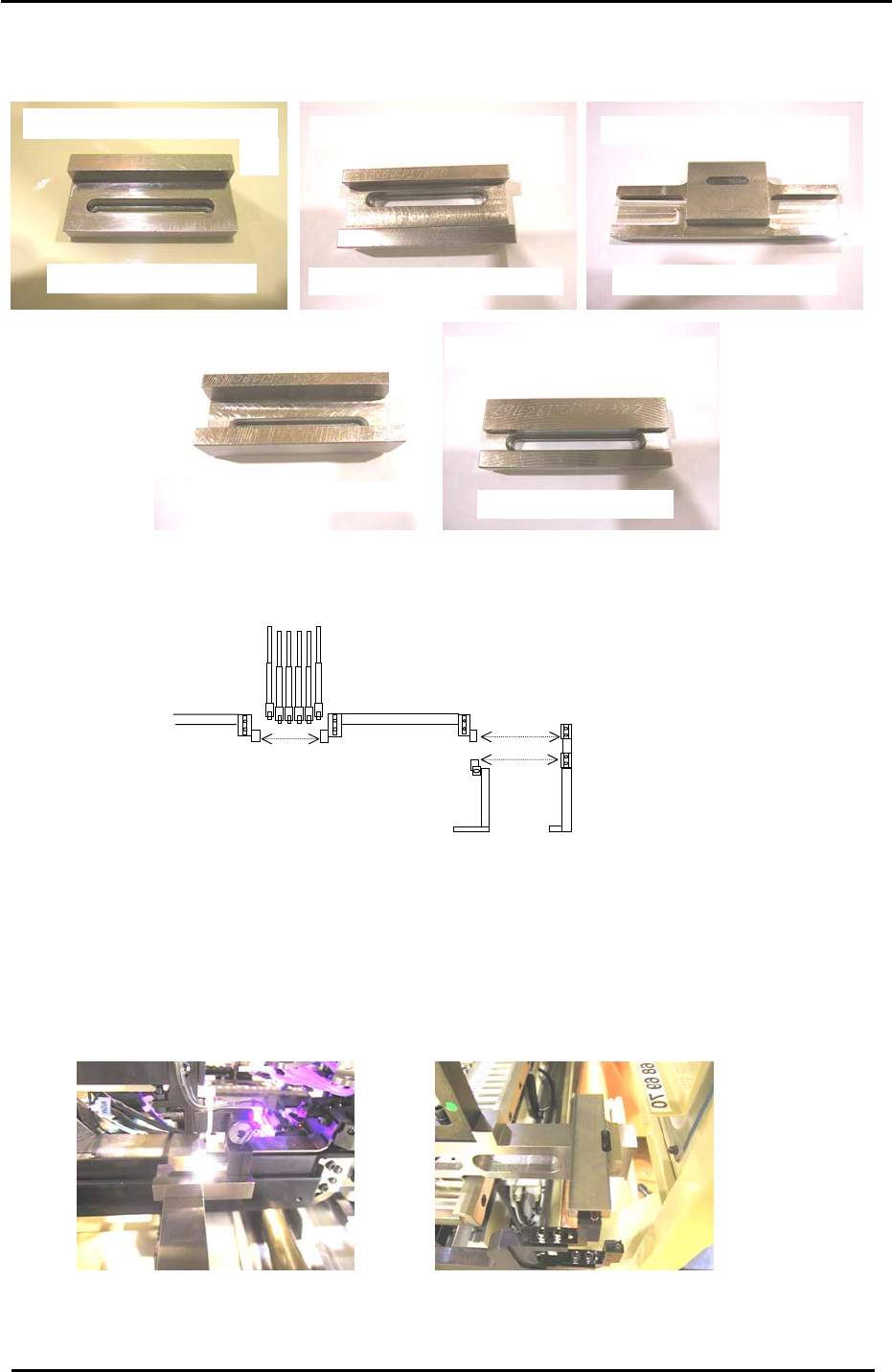
2. The jigs pictured in figure 27 are needed for sensor positioning adjustment.
A
DCPJ0040
(
CP-7 Series
)
Feeder U
p
sensor
p
ositionin
g
Ji
g
B
Feeder u
p
sensor
p
ositionin
g
Ji
g
DCPJ0050 CP732E
+
CP742ME
C
Feeder u
p
sensor
p
ositionin
g
j
i
g
DGPJ0040
(
CP742E Onl
y)
D
Feeder down sensor
p
ositionin
g
j
i
g
DCPJ0070
(
CP7 Series
)
E
Feeder down sensor
p
ositionin
g
j
i
g
DCPJ0060
(
CP7 Series
)
Figure 27
3. Refer to figure 28 below and the text that follows to determine which jig should be used for
which sensor:
Jig A should be used for sensors 1,2, and 3.
Jig B should be used for sensor 4 (CP-732/733E and CP-742ME)
Jig C should be used for sensor 4 (CP-742/743E only)
Jig D should be used for sensor 5.
Jig E should be used for sensor 6.
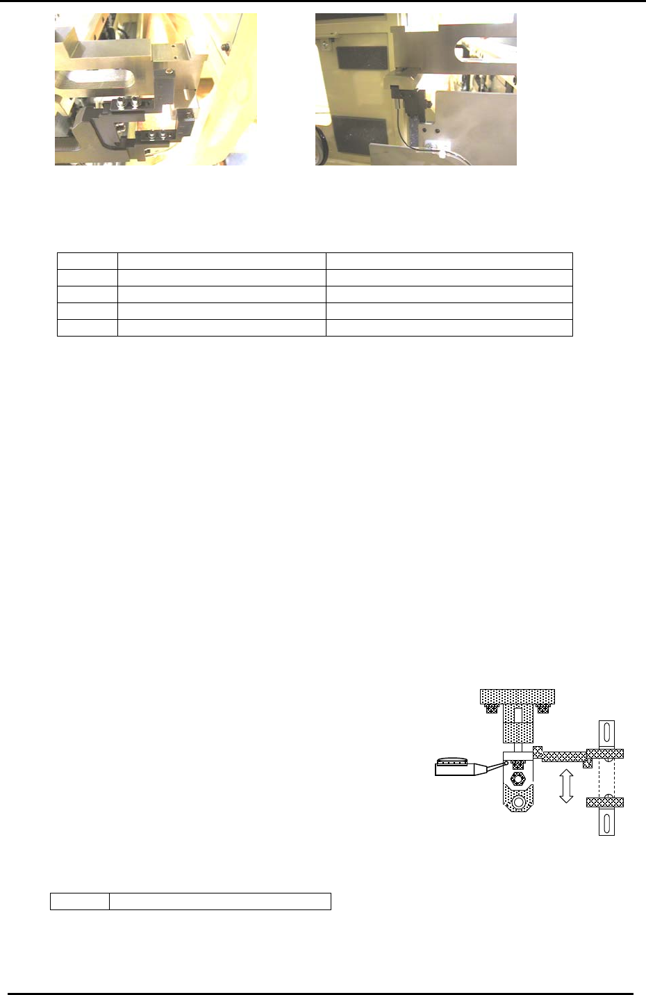
4. The various adjustments are pictured in figure 29 below:
Figure 28
Feeder Up and Down
sensors on the D axis.
6
5
34
1 2
A
lignment of sensor 1
A
lignment of sensors 1, 2, and 3
A
lignment of sensor 4 (CP742/743E Only)
Fuji Machine Mfg. Co., Ltd. (Okazaki)
SMT Equipment Quality Assurance Dept.
CS Section
4-18
FK-9F98-27 CP-7 Series Training Text for Service Engineers
Edition 6.0 Chapter 4. Station Adjustment [19/28]
Figure 29
A
lignment of sensor 6
A
lignment of sensor 5
5. Confirm sensor reaction by I/O.
<I/O Æ Standard Æ IN>
X042 TAPE LEAF CHECK (Tape guide lift check)
X043 D1 FEEDER CHECK UP (D1-axis feeder lift check – upper)
X044 D1 FEEDER CHECK DOWN (D1-axis feeder lift check – lower)
X054 D2 FEEDER CHECK UP (D2-axis feeder lift check – upper)
X055 D2 FEEDER CHECK DOWN (D2-axis feeder lift check – lower)
6. Set the Amplifier as follows:
Note: To unlock or lock the sensor amplifier, press the up or down key simultaneously with
the mode key for more than 3 sec.
a. Set the output switch to “L-ON”.
b. Press the mode key for more than 3 secondsÆ Turbo Æ select the “super” LED
(by using the up/down arrows) Æ Press the mode key once quickly Æ DLY (make sure
the “super” LED is ON) Æ Press the mode key once quickly Æ set to 200P by
using the up/down keys. Adjustment complete.
Note: There is never a need to press the SET button. Pressing the set button will change the
internal mode of the sensor amp.
4.16 Station 1 N times feeding Adjustments
4.16.1 Retract End Sensor Adjustment
Figure 30
1. With the cam at 0 degrees, turn ON the station 1
feeding solenoid valve. (Y033 TAPE FEED SOL
ENGAGED)
2. Rotate the cam axis and adjust the sensor bracket so
that the sensor turns OFF when the flag is 0.5mm lower
than the upper limit. Use a dial gauge to check.
3. Check sensor reaction by I/O.
<I/O Æ Standard Æ I/O>
X03C FEEDING RETRACT LIMIT
Fuji Machine Mfg. Co., Ltd. (Okazaki)
SMT Equipment Quality Assurance Dept.
CS Section
4-19
FK-9F98-27 CP-7 Series Training Text for Service Engineers
Edition 6.0 Chapter 4. Station Adjustment [20/28]
4.16.2 Forward End Sensor Adjustment
1. Move the feeding lever to the forward limit (the cam angle should be around 200 degrees)
and rotate the cam angle so that the flag ascends 0.5mm from the forward end sensor. Use a
dial gauge to check. Adjust the sensor bracket so that the sensor turns OFF at this position.
2. Check sensor reaction by I/O.
<I/O Æ Standard Æ IN>
X03B FEEDING FORWARD LIMIT
4.16.3 Speed Controller Adjustment
1. Fully open the speed controllers for the upper lower ends of the feed cylinder.
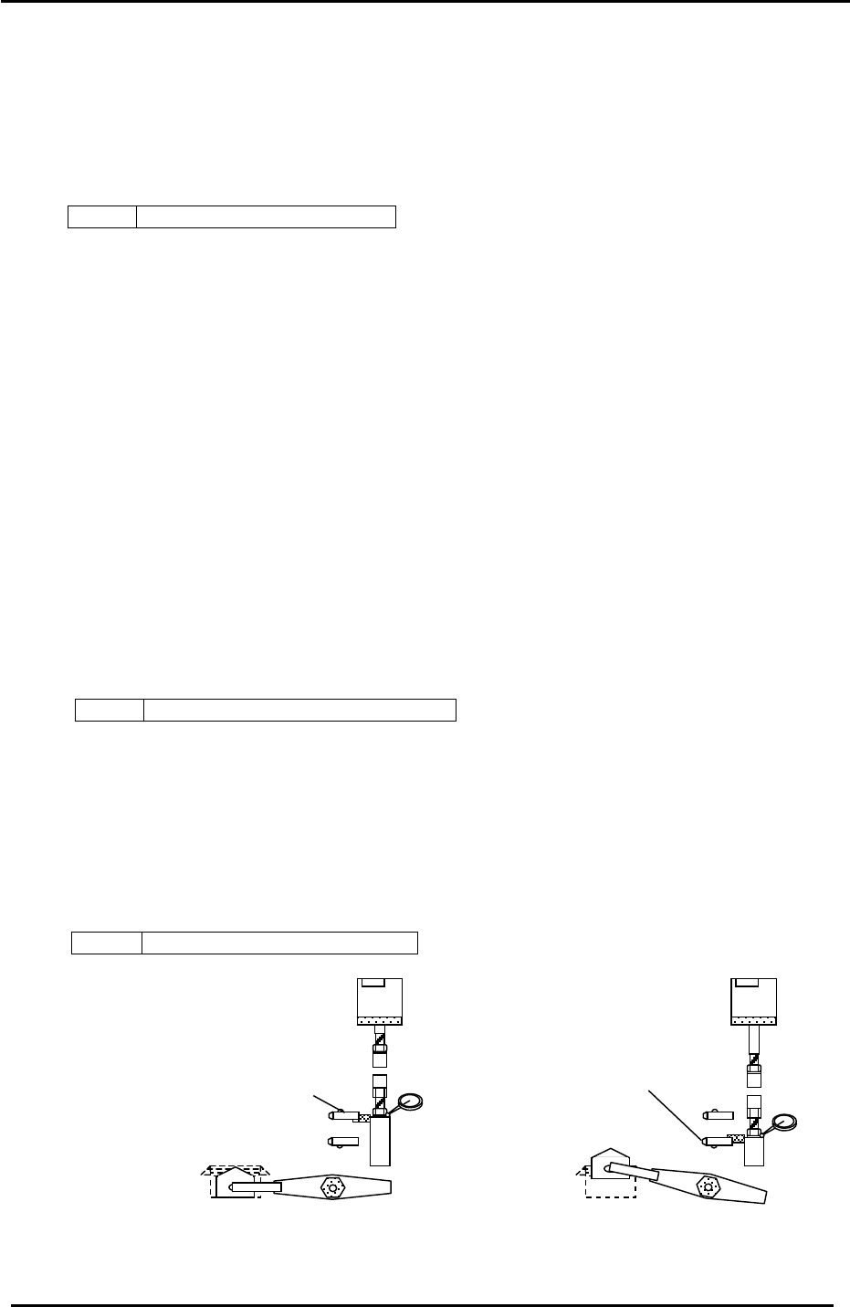
4.17 Station 1 N times Cutter Adjustment
1. At 0 degrees, turn the tape feeder solenoid valve OFF. (Y032) Set the dial gauge at the cam
angle where the flag starts descending from the upward position.
2. Rotate the cam axis and check the position where the flag descends 0.5mm from the upper
limit using a dial gauge. Adjust the sensor bracket so that the sensor turns OFF at this
position.
* The flag descends when the movable cutter raises. When the upper end sensor turns ON,
the movable cutter descends. Check the I/O as follows:
<I/O Æ Standard Æ IN>
X04E TAPE CUTTER LOWER LIMIT
3. Analogous to the above, when the movable cutter is at the upper limit (cam angle 190
degrees), rotate the cam axis and check the position where the flag ascends 0.5mm from the
lower limit by a dial gauge. Adjust the sensor bracket so that the sensor turns OFF at this
position.
*When the flag descends the lower sensor turns ON and the movable cutter raises. Check
the I/O as follows:
<I/O Æ Standard Æ IN>
X04D TAPE CUTTER UPPER LIMIT
Movable cutter upward sensor
X04D TAPE CUTTER UPPER-LIMIT
Movable cutter downward sensor
(X04E TAPE CUTTER LOWER-LIMIT)
<Moveable cutter lowered position>
<Moveable cutter raised
p
osition>
Figure 31
Fuji Machine Mfg. Co., Ltd. (Okazaki)
SMT Equipment Quality Assurance Dept.
CS Section
4-20