CP7 training(6.0) (1).pdf - 第71页
FK-9F98-27 CP-7 Series T raini ng T ext for Service Engineers Edition 6.0 Chapter 4. S tation Adjustment [22/28] Quality Assurance Dept. CS Section 4-22 NZ-axis serv o counter chart 0.002mm / Pulse S tandard (Reference) …
FK-9F98-27 CP-7 Series Training Text for Service Engineers
Edition 6.0 Chapter 4. Station Adjustment [21/28]
4. Set the cam at 0 degrees. Run the cutter for N times by I/O (Y03E n TAPE CUT), and perform
the sensor input and operation check.
*Speed controller volume: Both up & down flow controls are set to fully open.
Note: Carry out the solenoid valve operation for the N times cutter at 0 degrees.
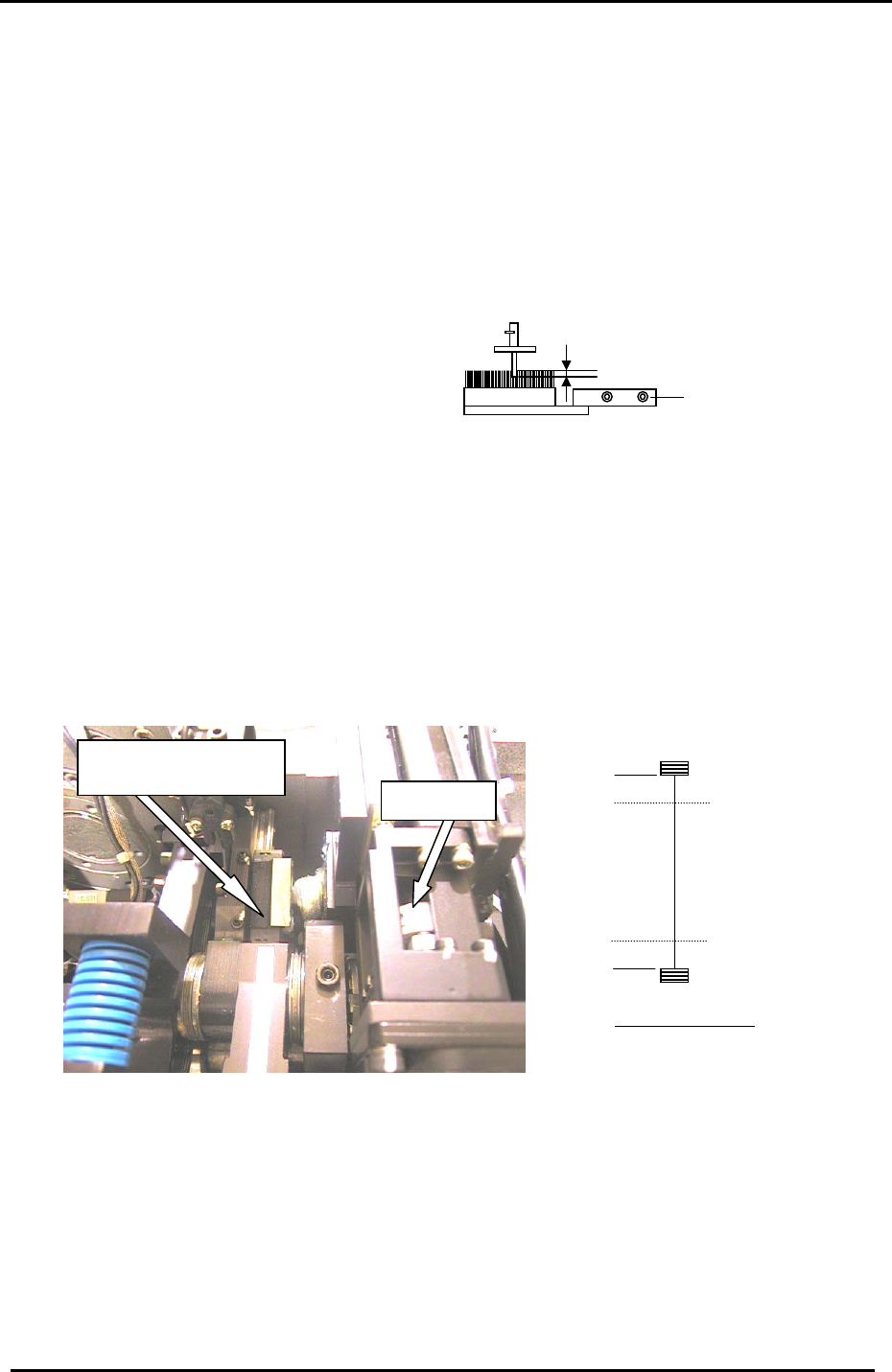
4.18 Station 13 Brush Height Adjustment for Parts Rejection
1. Set a nozzle in the holder and move it to station 13. Adjust the brush height so that the tip of the
nozzle jig enters the top surface of the brush by 0.5 to 1.0mm.
Installation bolts
0.5 to 1mm into the brush
4.19 Nozzle Holder Installation
1. Install the nozzle filters on all the shafts.
Fi
g
ure 32
2. Check the motion of the shafts and then install the holders on all the nozzle shafts.
3. Check the alignment of holder and jig by following the procedure outlined in step 4.1 at the
beginning of this chapter.
4.20 ST1 NZ Adjustment & Calibration Data Measurement
1. Loosen the coupling for the NZ-axis motor and move the guide to the minus mechanical
stopper. (figure 33)
Guide against the minus
mechanical stopper
NZ Coupling
Minus stopper
Plus stopper
Min Limit Pos.
100 Pulses
100 Pulses
Max Limit Pos.
Rear of Machine
Figure 33
2. Set the counter value to zero and tighten the coupling. (Torque setting: 0.8Nm)
3. Set the NZ Calibration Data as follows:
(Maximum Limit = 100 pulses from the + stopper)
Press: [Maintenance] → [Calibration] → [Travel Limits] →[Maximum Limit NZ]
(Minimum Limit = 100 pulses from the – stopper)
Press: [Maintenance] → [Calibration] → [Travel Limits] →[Minimum Limit NZ]
Fuji Machine Mfg. Co., Ltd. (Okazaki)
SMT Equipment Quality Assurance Dept.
CS Section
4-21
FK-9F98-27 CP-7 Series Training Text for Service Engineers
Edition 6.0 Chapter 4. Station Adjustment [22/28]
Quality Assurance Dept.
CS Section
4-22
NZ-axis servo counter chart
0.002mm / Pulse
Standard
(Reference)
+ Mechanical stopper 12770 ± 1000
Max Limit Pos NZ 12670 ± 500
Pickup Pos NZ 4000 ± 1000
Min Limit Pos NZ 100 ± 50
– Mechanical stopper 0 ± 50
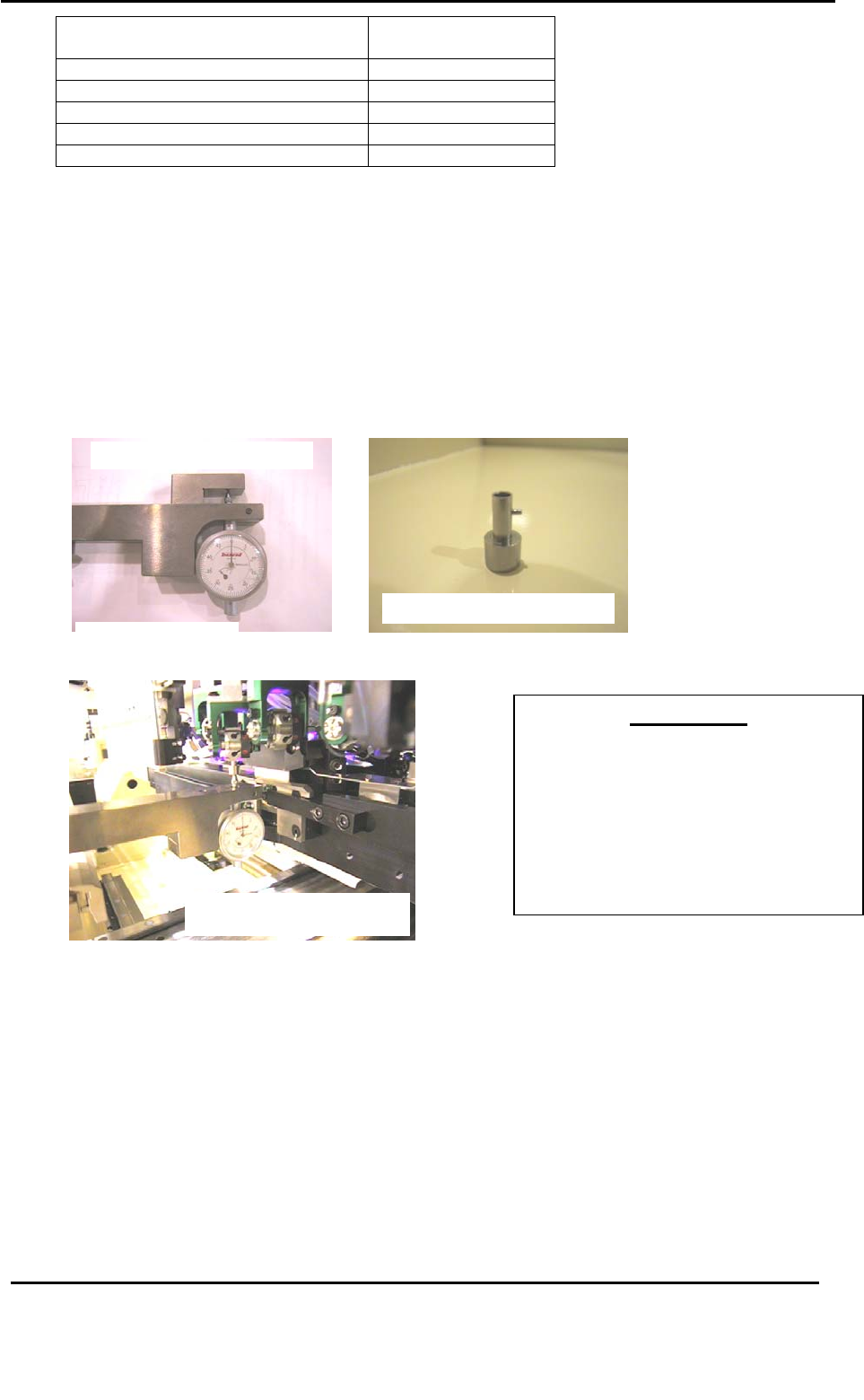
4.21 ST1 NZ Pick-Up Position Adjustment
1. Set the cam to 0 degrees and turn ON the ST1 nozzle UP/DOWN solenoid valve. (Y031)
2. Place the 1
st
nozzle height calibration jig on the D-axis pallet and install the
nozzle jig at nozzle holder No.1. Set the cam angle at 170 degrees and move the
NZ-axis manually so the nozzle jig descends until the pick up height is 0.65mm (at this
condition the dial gauge should read 0).
1
s
t
nozzle hei
g
ht calibration
j
i
g
JIG No. ADCPJ8261
Nozzle Jig. Jig No. DCPJ0620
Figure 34
1
s
t
nozzle height calibration jig
Jig No. ADCPJ8261
IMPORTANT!!
The pick-up height calibration is critically
important to ensuring stable pick-up. If
not adjusted correctly, damage to
components may occur (due to shock
from nozzle) or pick-up rates will not be
at optimum levels. Be sure to use care
when making adjustments in this area.
Figure 35
3. Calibrate the NZ-axis servo counter value for all shafts (A through P) and record the value.
4. Calculate the average value for all shafts and set as the : PICK UP POS NZ.
Press: [Maintenance] → [Calibration] → [Pick Up Reference] → [NZ Original Pos.] → [Set]
*Measurements should be carried out at device locations (2 & 29, CP-732/733E), (2 &
39, CP- 742/743ME), (2 & 69, CP-742/743E) on both pallets.
Target Value: 0.65 ± 0.05mm
Fuji Machine Mfg. Co., Ltd. (Okazaki)
SMT Equipment
FK-9F98-27 CP-7 Series Training Text for Service Engineers
Edition 6.0 Chapter 4. Station Adjustment [23/28]
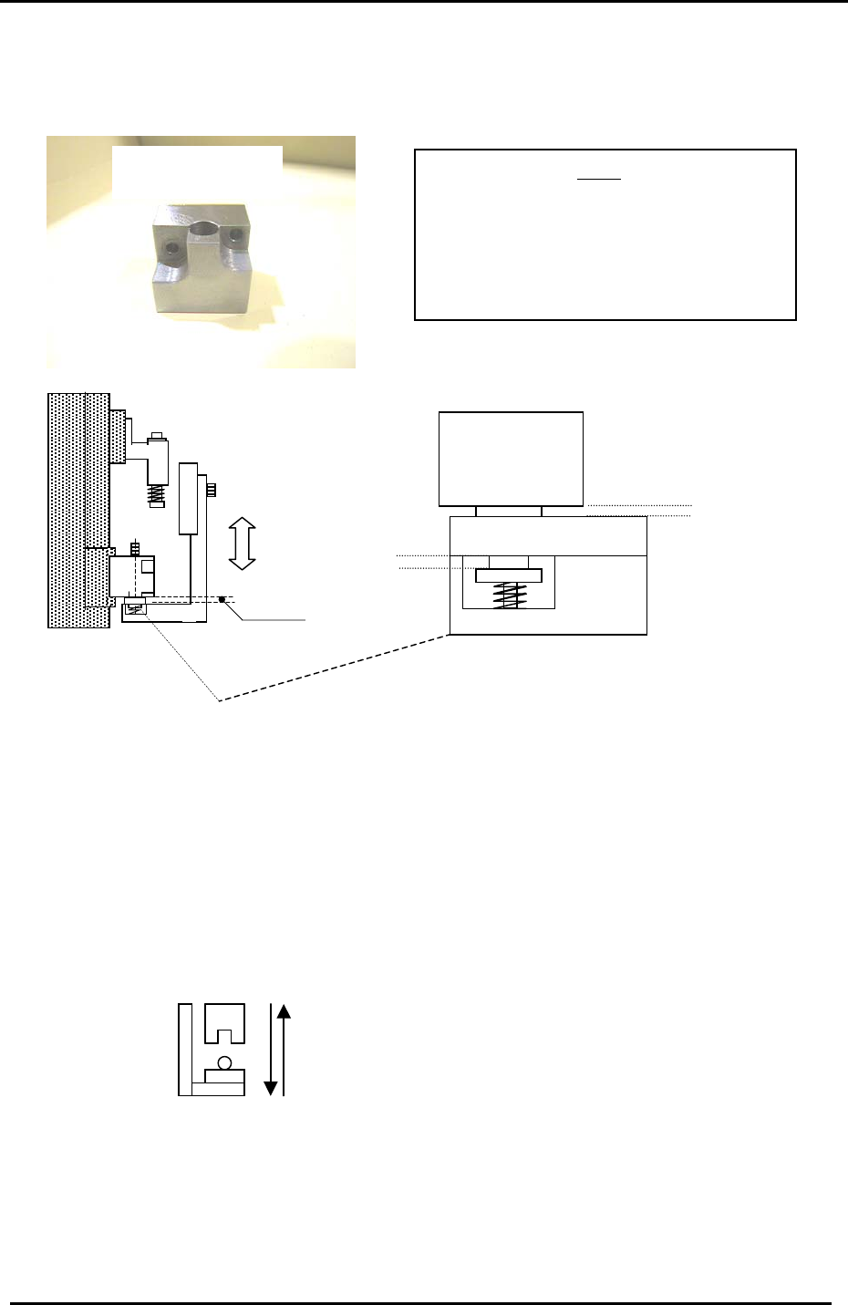
4.22 Station 9 Mechanical Valve Adjustment Check
1. Remove the spool valve from shaft “A “and install the valve alignment jig.
Mechanical Valve Jig
Jig No. DGPJ6610
Note:
Place the dial gauge on the right side of the
“Low Valve” and set to 0. Remove the valve
and install the alignment jig at the same
position the valve was located. All valves
should be within 0.1mm of each other.
Refer to Sec. 3.16, page 3-32 step 6.
1.9mm
Figure 36
0.1mm
1.9mm
Clearance Check
Valve
2. With the cam at 0 degrees turn the 9
th
station place solenoid OFF. (Y034)
3. Disconnect the air.
4. Move the cam angle to 195 degrees.
5. Loosen the forward and backward positioning bolts for the 9
th
station bracket.
6. Adjust the 9
th
station bracket so that the small round bracket notch goes directly into the jig hole.
You can check if it is properly inserted by moving the bracket. If it is completely inside, the
bracket will not move.
Side View
7. Once finished, remove the jig and reconnect the air at 0 degrees.
8. Turn the 9
th
station place solenoid ON (Y035) and install the spool valve on shaft A. Ensure the
spool valve is in the same position as the spool valve on the B shaft. (use the X-axis pulse
counter with the cam at 195 degrees and measure using a dial gauge.
Fuji Machine Mfg. Co., Ltd. (Okazaki)
SMT Equipment Quality Assurance Dept.
CS Section
4-23