CP7 training(6.0) (1).pdf - 第74页
FK-9F98-27 CP-7 Series T raini ng T ext for Service Engineers Edition 6.0 Chapter 4. S tation Adjustment [25/28] c. Align bracket (1) parallel to the D-axis by adjusting the bracket as shown in fig. 40. (T ol: < 0.1mm…
FK-9F98-27 CP-7 Series Training Text for Service Engineers
Edition 6.0 Chapter 4. Station Adjustment [24/28]
9. Next, bring the shaft with the lowest spool to the 9
th
station at 195 degrees.
10. Set the gap between the spool and bracket to 0.1mm using a feeler gauge ( figure 36 above).
11. Set the flow controller as follows: For the rough adjustment of the flow controller, set 5 turns
from fully closed. For fine adjustment, set the cam at 195 degrees with the
highest valve at
station 9. Turn ON (I/O: Y03A Air Blow) Using a manometer, set the air pressure to 113+/-
3mmHg. (15.0+/-0.5 kPa)
4.23 Station 1 Mechanical Valve Adjustment
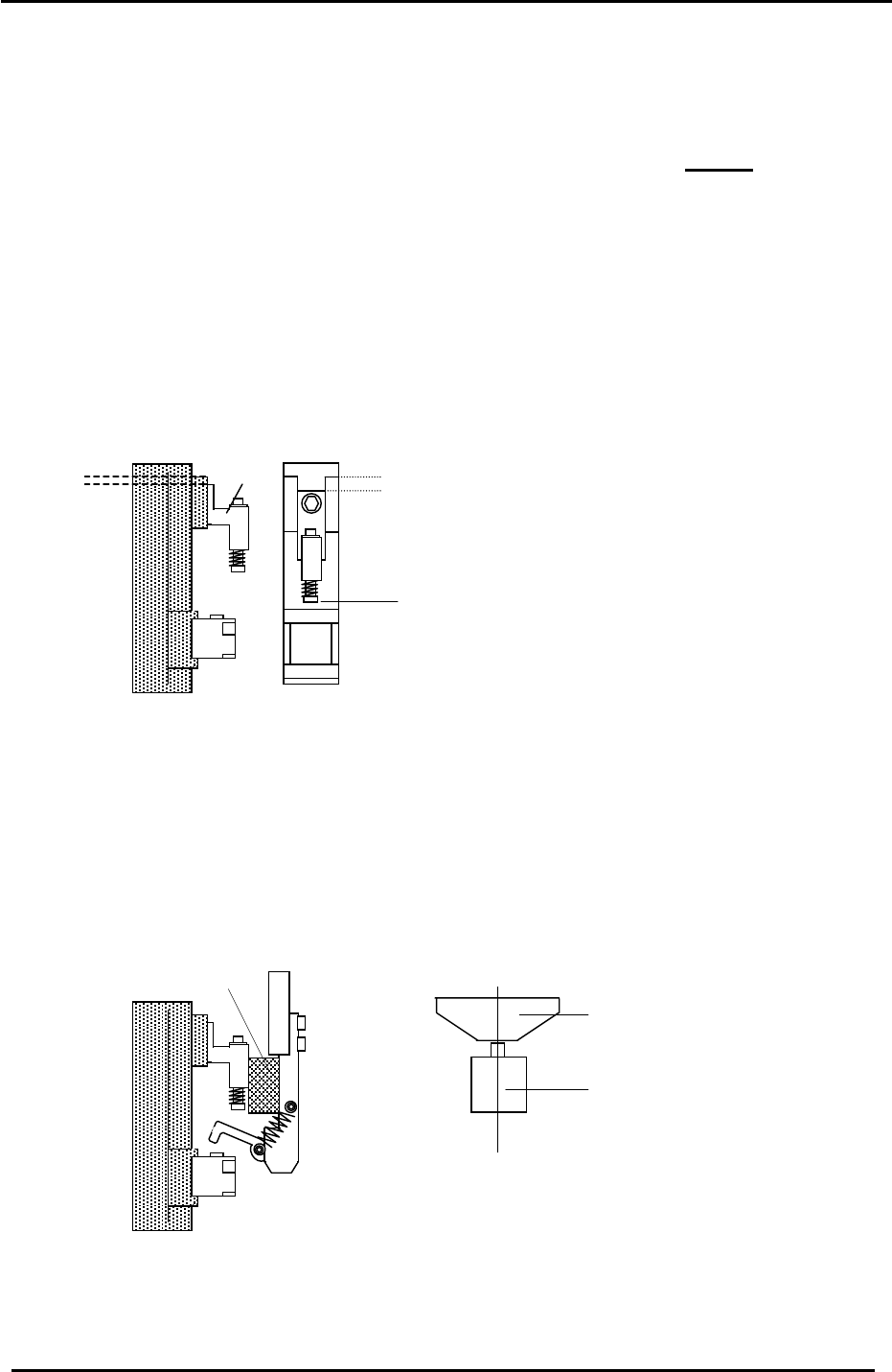
1. Adjust all shafts so that the gap between the spring pin BKT (1) top surface and support BKT
top surface is 2.3mm. (A) Note: all spring pin heights should be within 0.1mm of each other.
Figure 37
2.3mm
(1)
A
The spring pin height on shafts
A to P should be within 0.1mm.
2. Set the mechanical valve switch lever alignment as follows:
a. Adjust the clearance between the spring pin bracket and lever bracket using a 12mm
spacer jig. (figure 38). (Jig. No. ADCPJ8150)
b. Align the vacuum switching lever and mechanical valve as illustrated with the cam at 170
degrees. (figure 39).
8 Figure 3
12mm spacer jig
Valve Switching
Lever
Valve
C
L
Figure 39
Fuji Machine Mfg. Co., Ltd. (Okazaki)
SMT Equipment Quality Assurance Dept.
CS Section
4-24
FK-9F98-27 CP-7 Series Training Text for Service Engineers
Edition 6.0 Chapter 4. Station Adjustment [25/28]
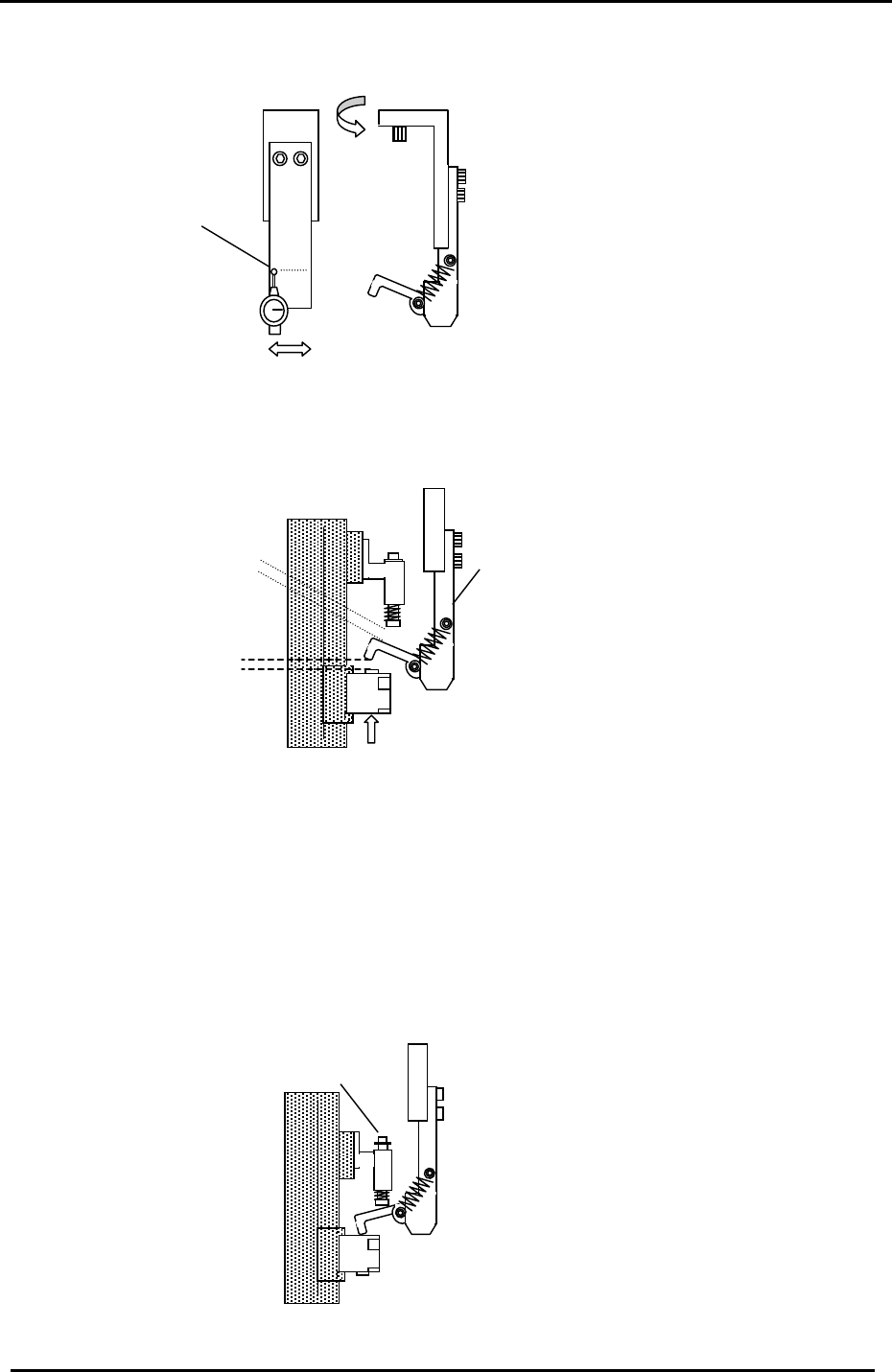
c. Align bracket (1) parallel to the D-axis by adjusting the bracket as shown in fig. 40.
(Tol: < 0.1mm)
1
Figure 40
< 0.1mm
3. Turn the station 1 pick up solenoid valve OFF (Y031) and move the reference shaft (the shaft
with the lowest spool position) to station 1 and set the cam to 170 degrees.
4. Adjust the lever BKT (2) so the clearance between the spring pin and lever becomes 0.6mm.
<Station 1 mechanical valve adjustment check>
Check the following after station 1 mechanical valve adjustment
Figure 41
(2)
0.6mm
0.4 to 0.7mm
clearance check
1. With the cam at zero degrees, turn the pick up solenoid valve ON. (Y031)
2. Set the NZ to its minimum stroke: (pick up pos. NZ-2619 pulses) and set the cam angle to
170 degrees. Check that the spring type pin (1) is pushed up slightly.
[Note]: Confirm that there is no interference when the NZ-axis is moved through full stroke.
(1)
Figure 42
Fuji Machine Mfg. Co., Ltd. (Okazaki)
SMT Equipment Quality Assurance Dept.
CS Section
4-25
FK-9F98-27 CP-7 Series Training Text for Service Engineers
Edition 6.0 Chapter 4. Station Adjustment [26/28]
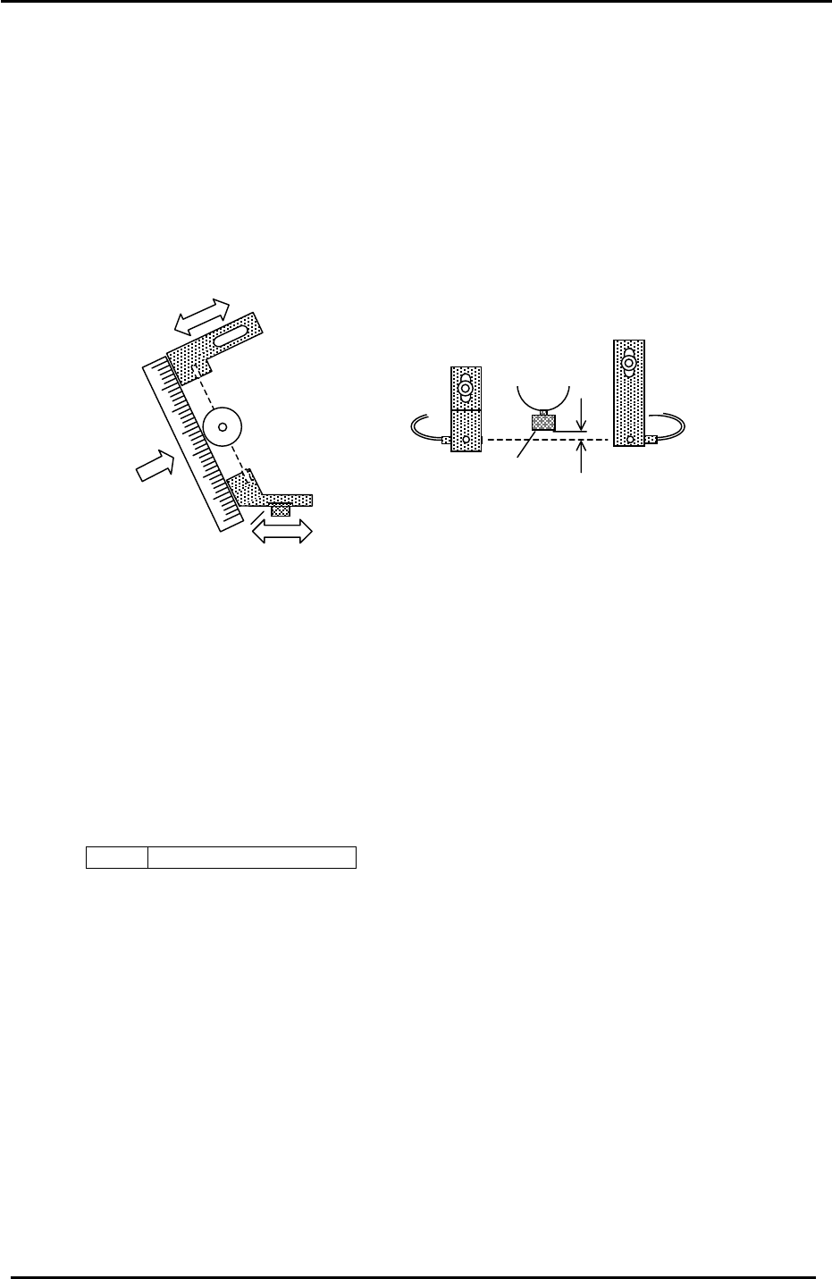
4.24 Station 2 Large Parts Check Sensor Adjustment
1. Set the A shaft at station 2 and set the cam to 200 degrees.
2. Install a 0.7 nozzle and align the brackets so the emitter / receiver and 8mm nozzle disk align.
3. Next, position the emitting and receiving sensors so the beam is aligned with the center of the
nozzle.
4. By adjusting the brackets, set the height of the emitter and receiver so the light beam passes
0.7 to 0.8mm below the jig.
1
Receiver
Emitter
2
3
Figure 43
8mm nozzle disk
0.7 to 0.8mm
5. Set the Amplifier as follows:
a. Set the output switch to “D-ON”.
b. Press the mode key for more than 3 secondsÆ Turbo Æ select the “super” LED
(by using the up/down arrows) Æ Press the mode key once quickly Æ DLY (make sure the
“super” LED is ON) Æ Press the mode key once quickly Æ set to 200P by
using the up/down keys. Adjustment complete.
Note: There is never a need to press the SET button. Pressing the set button will result in
changing the mode of the sensor amp.
<I/O Æ Standard Æ IN>
X036 ST2 Large Parts Check
Fuji Machine Mfg. Co., Ltd. (Okazaki)
SMT Equipment Quality Assurance Dept.
CS Section
4-26