CP7 training(6.0) (1).pdf - 第76页
FK-9F98-27 CP-7 Series T raini ng T ext for Service Engineers Edition 6.0 Chapter 4. S tation Adjustment [27/28] 4.25 St ations 1 & 9 Upw ard and Do wnward End Sensor Adjustment 1. At 0 degrees, turn ON the sole noid…
FK-9F98-27 CP-7 Series Training Text for Service Engineers
Edition 6.0 Chapter 4. Station Adjustment [26/28]
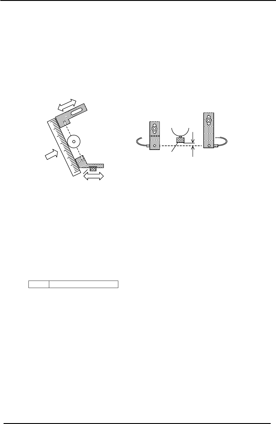
4.24 Station 2 Large Parts Check Sensor Adjustment
1. Set the A shaft at station 2 and set the cam to 200 degrees.
2. Install a 0.7 nozzle and align the brackets so the emitter / receiver and 8mm nozzle disk align.
3. Next, position the emitting and receiving sensors so the beam is aligned with the center of the
nozzle.
4. By adjusting the brackets, set the height of the emitter and receiver so the light beam passes
0.7 to 0.8mm below the jig.
1
Receiver
Emitter
2
3
Figure 43
8mm nozzle disk
0.7 to 0.8mm
5. Set the Amplifier as follows:
a. Set the output switch to “D-ON”.
b. Press the mode key for more than 3 secondsÆ Turbo Æ select the “super” LED
(by using the up/down arrows) Æ Press the mode key once quickly Æ DLY (make sure the
“super” LED is ON) Æ Press the mode key once quickly Æ set to 200P by
using the up/down keys. Adjustment complete.
Note: There is never a need to press the SET button. Pressing the set button will result in
changing the mode of the sensor amp.
<I/O Æ Standard Æ IN>
X036 ST2 Large Parts Check
Fuji Machine Mfg. Co., Ltd. (Okazaki)
SMT Equipment Quality Assurance Dept.
CS Section
4-26
FK-9F98-27 CP-7 Series Training Text for Service Engineers
Edition 6.0 Chapter 4. Station Adjustment [27/28]
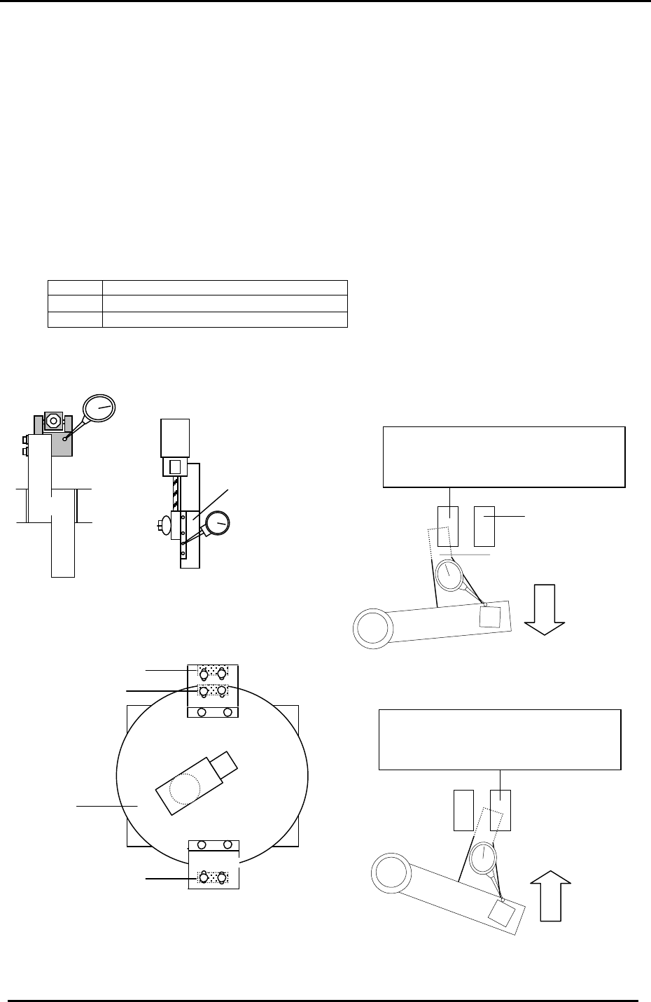
4.25 Stations 1 & 9 Upward and Downward End Sensor Adjustment
1. At 0 degrees, turn ON the solenoid valve for Stations 1 & 9
nozzle up/down.
2. For Stations 1& 9 Up End sensor adjustment, set the cam at 0 degrees. Set a dial indicator at
the tip of the cam lever. Adjust the sensor bracket so that the upper limit sensor turns OFF
when the lever descends 0.30 to 0.40mm.
3. For the Station 9 Down End sensor adjustment, set the cam at 195 degrees. Set the dial
gauge at the tip of the cam lever. Adjust the downward end sensor to turn OFF when the lever
ascends 0.30 to 0.40mm.
4. Confirm sensor reaction by I/O.
<I/O Æ Standard Æ IN>
X030 ST1 NOZZLE UPPER LIMIT CHECK
X032 ST9 NOZZLE UPPER LIMIT CHECK
X033 ST9 NOZZLE LOWER LIMIT CHECK
Note: For further information and illustrations on this procedure, refer to the CP-7 series Mechanical
Reference Manual.
Station 9
NZ
Sensor flag
Down end sensor
The up end sensor should turn
OFF when the lever lowers 0.3 to
0.4mm from 0 de
g
rees.
Station 1
Noz. Up/Down
Figure 46
Down end sensor
Up end sensor
Station 9
Station 1
Nozzle index unit
Up end sensor
Figure 47
Figure 48
Figure 49
The down end sensor should turn
OFF when the lever lifts 0.3 to
0.4mm from 195 de
g
rees.
Fuji Machine Mfg. Co., Ltd. (Okazaki)
SMT Equipment Quality Assurance Dept.
CS Section
4-27
FK-9F98-27 CP-7 Series Training Text for Service Engineers
Edition 6.0 Chapter 5. Loader and Conveyor Adjustment [9/28]
5.13 Z-axis Mechanical Valve Adjustment
1. Adjust the mechanical valve and dog for the moveable rail locking cylinders as follows.
The moveable rail on the main table should lock when the Z-axis is positioned at;
[ZL lower – 650 +/- 50 pulses.]
2. If out of range, move the dog up or down until the rail clamps within the specified range.
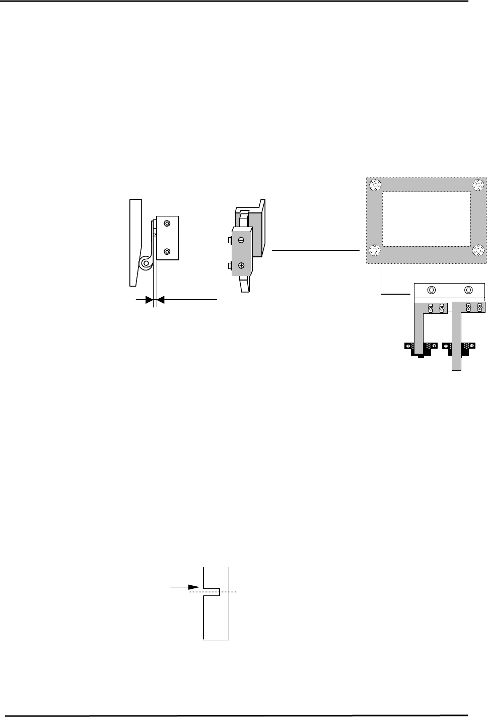
3. After adjustment, make sure the pneumatic swich lever has 1 to 2mm of play. Too much
pressure on the lever will result in damage to the pneumatic switch.
5.14 Z-axis Sensor Adjustment
MOT Sensor
X05E MAIN LIFTER
MIDDLE OT
1 to 2mm
Figure 16
Upper end limit
X05C XY-TABLE LOADING
HEIGHT CHECK
1. Set the middle overtravel sensor flag at [ Z0 + 250 ± 50pls.]
2. Calculate the Middle Loading Position as follows:
CP-732/733E [ML= ZL Lower – 9250 ± 50pls.]
Note: this is a Calibration Data item for the Middle Load Pos.
CP-742/743(M)E [ML= ZL Lower – 14000 ± 50pls.]
Note: this is a Calibration Data item for the Middle Load Pos.
3. To set the Calibration Data for the Middle Loading Position, Press: [Maintenance] →
[Calibration] → [Loading Position] → [Middle Loading Position] → [Set]
4. Set the upper end sensor limit flag at: [ ML - 125 ± 50pls.]
5. Ensure the flags are centered within the sensors after adjustment.
Move the flag to trigger
the sensor at this edge.
Middle Load Position
Figure 17
Fuji Machine Mfg. Co., Ltd. (Okazaki)
SMT Equipment Quality Assurance Dept.
CS Section
5-9