CP7 training(6.0) (1).pdf - 第8页
FK-9F98-27 CP-7 Series T raini ng T ext for Service Engineers Edition 6.0 Chapter 2. Cam Box Adjustm ent [1/8] Chapter 2 Cam Box Checks and Adjustment s 2.1 Interference Check 1. With the cam angle at 0 degrees, check al…
FK-9F98-27 CP-7 Series Training Text for Service Engineers
Edition 6.0 Chapter 1. Initial Set-up [3/4]
1.4 Configuring the Machine Network Settings
After installation of the recovery and application software, it is necessary to set up the network
settings at the machine. All setting data is cleared from the machine once the recovery disk has
been used. Carry out the procedure below in order to establish communications with the host
PC.
1. After the machine boots from recovery and application software installation, press the
following commands to enter the network settings.
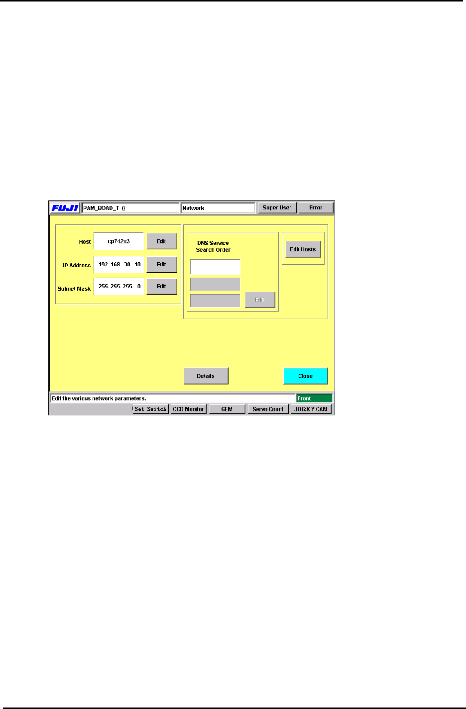
[Maintenance] → [System] → [Network]
2. Enter the machine Nickname (Host), IP address and Subnet Mask.
(This information should be provided by the network administrator at the user site.)
Figure 2
3. After setting the above, close the window and save the changes. It is now necessary to re-
boot the machine in order for the data to be registered.
4. After the machine has been re-booted, transmit the appropriate calibration data and
programs to the machine. After doing so, it will be necessary once again to re-boot the
machine.
Fuji Machine Mfg. Co., Ltd. (Okazaki)
SMT Equipment Quality Assurance Dept.
CS Section
1-3
FK-9F98-27 CP-7 Series Training Text for Service Engineers
Edition 6.0 Chapter 2. Cam Box Adjustment [1/8]
Chapter 2 Cam Box Checks and Adjustments
2.1 Interference Check
1. With the cam angle at 0 degrees, check all stations for interference before turning the cam.
2. As a precaution, it is best not to connect the air supply before adjustment of step 2.8 as some
stations may interfere if the air cylinders are not adjusted correctly.
3. Lower the vacuum switching brackets at stations 9 and 13 to ensure sufficient clearance when
the cam is rotated.
4. Check for interference between the various sensors and their flags before rotating the cam. Pay
special attention to station 1 and station 9 nozzle up & down detection sensors and flags located
in the cam box. Also, check the station 1 waste tape cutter upper and lower limit detection
sensors located (near the dump parts box) at station 13.
5. Secure the station 1 vacuum switching lever so that it does not interfere with the top surface of
the mechanical valve.
2.2 Cam Box Check
1. Check for any dust, tools, or other foreign matter within the Cam box.
2. Perform an initial check of all bolts and connectors to ensure they are tight.
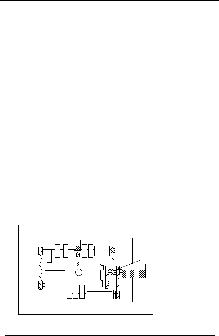
2.3 Securing the Motor Coupling and Mechanical Locks
1. Use a torque wrench to tighten the motor coupling and mechanical locks.
A: Motor Coupling 32.3N.m
B: Mechanical Lock (M4) 4.9N.m
C: Mechanical Lock (M5) 8N.m
A
C
B
B
B
B
Figure 1
Fuji Machine Mfg. Co., Ltd. (Okazaki)
SMT Equipment Quality Assurance Dept.
CS Section
2-1
FK-9F98-27 CP-7 Series Training Text for Service Engineers
Edition 6.0 Chapter 2. Cam Box Adjustment [2/8]
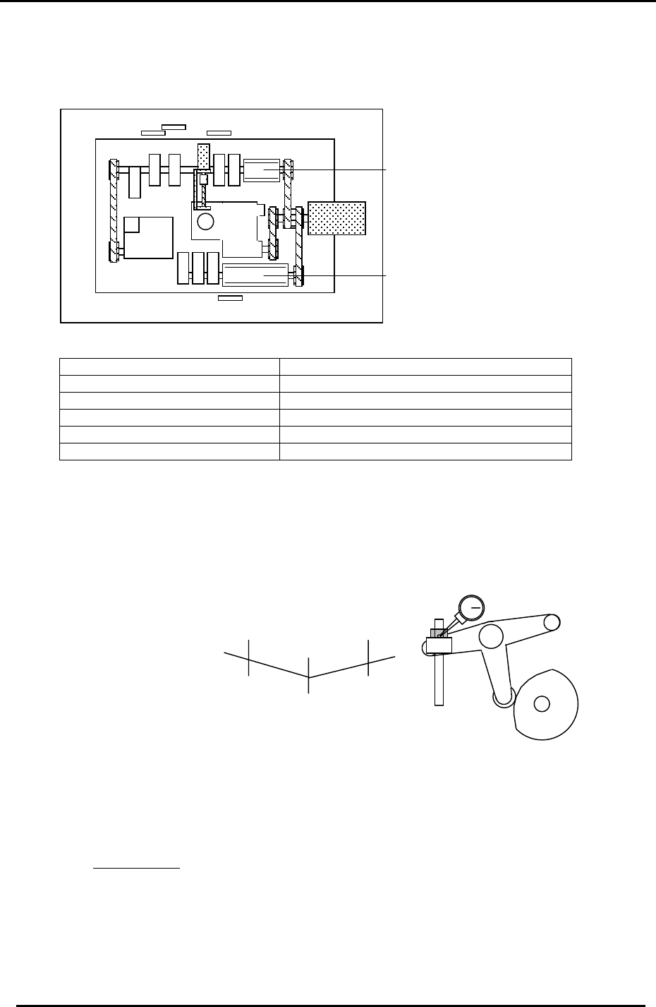
2.4 Cam Lever and Solenoid Valve Layout
Cam Box cam levers and valve locations are illustrated here.
12
11
10
9
8
6 7
4 5
3
2
1
“B“ Cam
Figure 2
“A “ Cam
1. ST1 Cut 7. ST9 Up & Down Nozzle
2. ST14 Nozzle Change 8. ST8 Up & Down FQ
3. ST1 Fwd & Bwd Feeding jaw 9. 10SOL-7,8 ST14 Select Clutch
4. ST1 Up & Down Nozzle 10. 10SOL-3,4 ST1 Fwd & Bwd Feed Jaw
5. ST2 Up & Down PQ 11. 10SOL-1,2 ST1 Up & Down
6. ST10 Up & Down RQ 12. 10SOL-5,6 ST9 Up & Down
2.5 B-Cam Scale Angle Check (Timing Reference Point)
1. Set a dial indicator on the cam lever of the waste tape cutter (B-axis). Check that the
maximum diameter (low point) of the cam is set to: 194 degrees: CP-732/733E, (190
degrees: CP-742/743(M)E)
Figure 3
+0.01+0.01
194
190
(
187.5
)
(190)
(
742
(
M
)
E
)
198
(
192.5
)
Waste Tape Cutter
2. When measuring with the dial gauge, find the center point and move the cam lever
0.01mm as indicated above. If the setting is balanced, the readings should be as
indicated. However, if not, move the angle scale so the readings are within range.
IMPORTANT!
The Cam B axis scale is the reference point for all timing within the Cam Box. Be sure
this adjustment is carried out correctly. Otherwise, the machine timing will be adversely
affected.
Fuji Machine Mfg. Co., Ltd. (Okazaki)
SMT Equipment Quality Assurance Dept.
CS Section
2-2