CP7 training(6.0) (1).pdf - 第81页
FK-9F98-27 CP-7 Series T raining T ext for Service Engineers Edition 6.0 Chapter 5. Loader and Con veyor Adjustment [13/28] 5.17 IN and OUT Conveyor PCB Lif ter Adjustment 1. Ensure the distance betwe en the top of t he …

FK-9F98-27 CP-7 Series Training Text for Service Engineers
Edition 6.0 Chapter 5. Loader and Conveyor Adjustment [12/28]
10. Divide the total pulse count found in step 8, by half. The result should be around the
center of the silver sticker and close to the YL pulse count. (Check the YL Calibration
Data) If not, adjust the sensor head position accordingly. (Balance is the key point)
11. Set the Z- axis at the minus stopper. Set the sensor to the B mode, by pressing the mode and
up keys quickly. Using the “B” mode, set the sensor sensitivity to 100P.
12. Return to the “A” mode and check the sensor performance while raising and lowering the main
table. If problems exist, repeat the procedure outlined above.
13. Lock the sensor settings by pressing both the up and mode keys simultaneously for more than
3 seconds.
<I/O → Standard → IN>
X0C0 Adjusting Rail Engagement Check IN
X0DB Adjusting Rail Engagement Check OUT
X0DC Adjusting Rail Engagement Check Center
Fuji Machine Mfg. Co., Ltd. (Okazaki)
SMT Equipment Quality Assurance Dept.
CS Section
5-12
FK-9F98-27 CP-7 Series Training Text for Service Engineers
Edition 6.0 Chapter 5. Loader and Conveyor Adjustment [13/28]
5.17 IN and OUT Conveyor PCB Lifter Adjustment
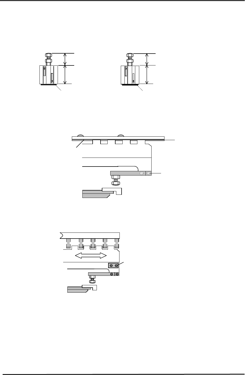
1. Ensure the distance between the top of the cylinder and the tip of the rod bolt is set
as illustrated.
(CP
-
732/733E)
(C
P-742
/
74
3(
M
)
E
)
IN 20mm, OUT 22mm
IN & OUT 25.7mm
2mm Spacer
48mm
48mm
2mm
Spacer
Figure 22
2. Lower the PCB lifter for the IN/OUT conveyor and adjust the lifter plate (after
loosening the mounting screws) to align with the center of the conveyor belt.
Lifter Plate
Mounting Screws
Conveyor belt
C
L
Figure 23
3. Move the IN and OUT carriers to the backward end position. Loosen the lifter plate mounting
screws and adjust so the clearance between the carrier claws and lifter plate is uniform.
Figure 24
Mounting Screws located
at both ends of the lifter plate.
(accessible with the lifter down)
4. To set the lifter height, place a board on the In conveyor, open the carrier claws, raise the lifter,
close the carrier claws and lower the lifter. (The Pcb is now held by the carrier)
Fuji Machine Mfg. Co., Ltd. (Okazaki)
SMT Equipment Quality Assurance Dept.
CS Section
5-13
FK-9F98-27 CP-7 Series Training Text for Service Engineers
Edition 6.0 Chapter 5. Loader and Conveyor Adjustment [14/28]
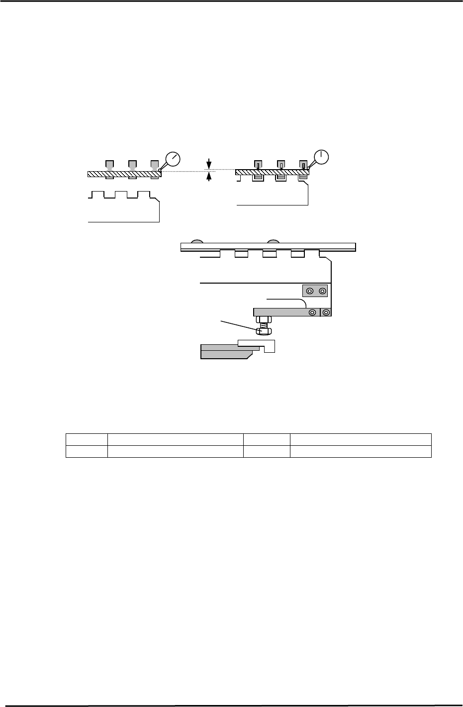
5. Raise the lifter when the carrier claw clamps the board.
Set a dial gauge on the board as illustrated (two gauges are recommended) Since the dial
gauge cannot normally read 1.2mm, use a 1mm feeler gauge when setting up the dial gauge
before raising the lifter. (Set 1 end first, then the other)
When the lifter is raised, the dial gauge should read 0.2mm +/-0.1mm. If out of tolerance, adjust
the four bolts as indicated.
After adjustment, the lifter should raise the Pcb off the carrier claws by 1.2mm.
0 (using 1mm feeler gauge)
0.2 +/- 0.1 (when lifter is raised)
<Lifter Up>
<Lifter Down>
1.20mm
Figure 25
Upper end adjustment bolt (x 4)
Figure 26
.
6. For the lifter cylinder sensors, turn both the up and down end sensors ON first. Set the sensors
at a position 0.5mm further in towards the ON position.
<I/O → Standard → IN>
X0B5 In-Lifter Upper limit Check X0D0 Out-Lifter Upper Limit Check
X0B6 In-Lifter Lower Limit Check X0D1 Out-Lifter Lower Limit Check
Fuji Machine Mfg. Co., Ltd. (Okazaki)
SMT Equipment Quality Assurance Dept.
CS Section
5-14