CP7 training(6.0) (1).pdf - 第85页
FK-9F98-27 CP-7 Series T raining T ext for Service Engineers Edition 6.0 Chapter 5. Loader and Con veyor Adjustment [17/28] 5.21 Claw Open -End Sensor Adjustment 1. Set the carrier at the retract position. 2. Set the len…
FK-9F98-27 CP-7 Series Training Text for Service Engineers
Edition 6.0 Chapter 5. Loader and Conveyor Adjustment [16/28]
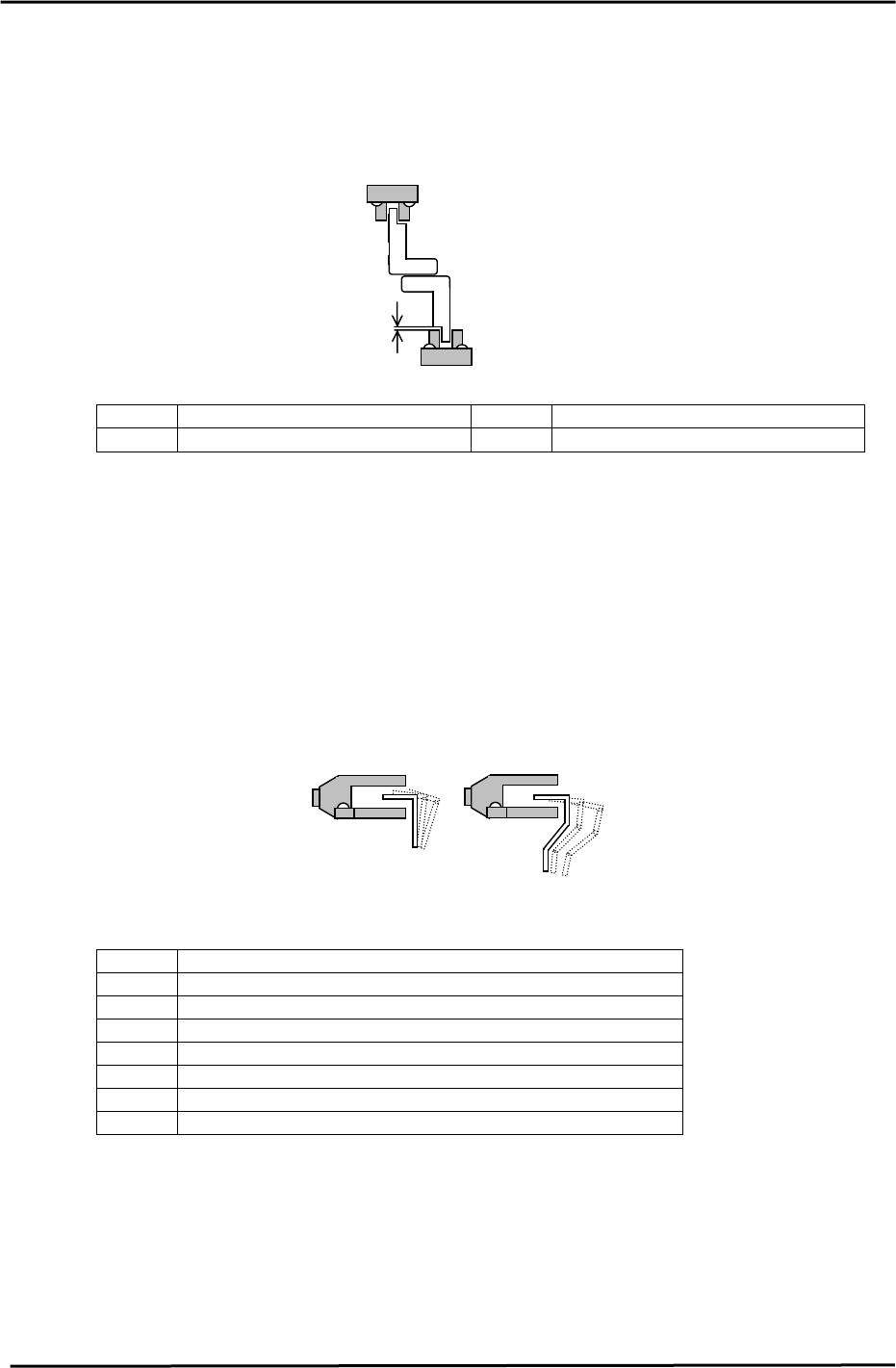
5.19 Advance / Retract End Sensor Adjustment
1. Adjust the Advance and Retract End sensor height so the clearance between the top of the
sensor and dog is 1mm.
2. Align the center of the sensor with the dog in the X and Y directions.
<I/O → Standard → IN>
1mm
Figure 28
X0B3 In-carrier Forward Limit Check X0CE Out-carrier Forward Limit Check
X0B4 In-carrier Retract Limit Check X0CF Out-carrier Retract Limit Check
5.20 Claw Closed-End Sensor Adjustment
1. Close the carrier claws to turn the sensor ON. Move the sensor 1mm toward the ON position and
secure.
2. Align the center of the sensor with the dog in the X- direction.
As for the height, be careful to avoid any interference with the flag and sensor when opening and
closing the carrier claws.
Figure 29
<I/O → Standard → IN>
X0B7 In-carrier Retract Limit Clamp Check (Fixed Rail)
X0B8 In-carrier Retract Limit Clamp Check (Adjustable Rail)
X0B9 In-carrier Forward Limit Clamp Check (Fixed Rail)
X0BA In-carrier Forward Limit Clamp Check (Adjustable Rail)
X0D2 Out-carrier Retract Limit Clamp Check (Fixed Rail)
X0D3 Out-carrier Retract Limit Clamp Check (Adjustable Rail)
X0D4 Out-carrier Forward Limit Clamp Check (Fixed Rail)
X0D5 Out-carrier Forward Limit Clamp Check (Adjustable Rail)
Fuji Machine Mfg. Co., Ltd. (Okazaki)
SMT Equipment Quality Assurance Dept.
CS Section
5-16
FK-9F98-27 CP-7 Series Training Text for Service Engineers
Edition 6.0 Chapter 5. Loader and Conveyor Adjustment [17/28]
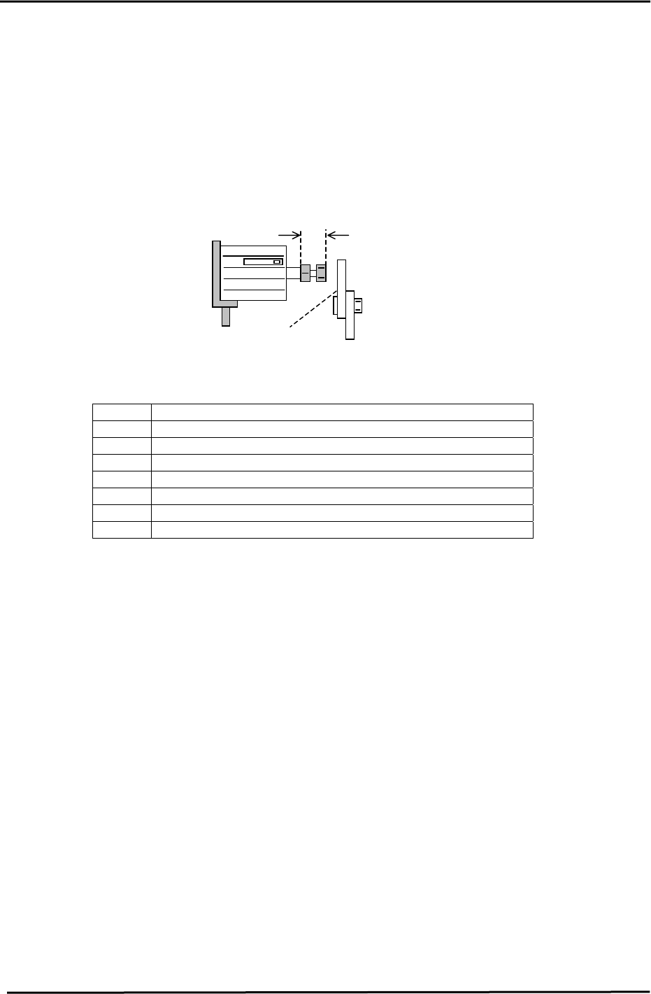
5.21 Claw Open -End Sensor Adjustment
1. Set the carrier at the retract position.
2. Set the length of the cylinder rod to 9mm. (Retract position only)
3. Align the cylinder bolt with the center of the Open-Close lever.
4. Open the carrier claws. Find the edge of the sensor ON position and move the sensor
0.5mm in the ON direction and secure.
9mm
Open-close lever
Figure 30
<I/O → Standard → IN>
X0BB In-carrier Retract Limit Unclamp Check (Fixed Rail)
X0BC In-carrier Retract Limit Unclamp Check (Adjustable Rail)
X0BD In-carrier Forward Limit Unclamp Check (Fixed Rail)
X0BE In-carrier Forward Limit Unclamp Check (Adjustable Rail)
X0D6 Out-carrier Retract Limit Unclamp Check (Fixed Rail)
X0D7 Out-carrier Retract Limit Unclamp Check (Adjustable Rail)
X0D8 Out-carrier Forward Limit Unclamp Check (Fixed Rail)
X0D9 Out-carrier Forward Limit Unclamp Check (Adjustable Rail)
Fuji Machine Mfg. Co., Ltd. (Okazaki)
SMT Equipment Quality Assurance Dept.
CS Section
5-17
FK-9F98-27 CP-7 Series Training Text for Service Engineers
Edition 6.0 Chapter 5. Loader and Conveyor Adjustment [18/28]
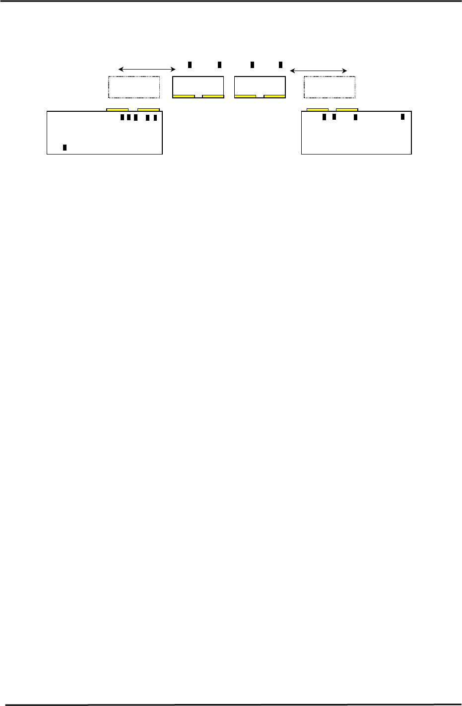
5.22 PCB Check Sensor Arrangement
IN Conveyor
IN Carrier OUT Carrier
OUT Conveyor
14
12
11
13
91078
6
5
23 4
1
PCB confirmation Sensors (Front view)
Figure 40
PCB Check Sensor location and function
1. Prevents boards that are longer than the M/C specification from being processed.
2. IN 2 Speed Reduction Check Sensor
2nd PCB speed reduction
3. IN 2 Arrival Check Sensor
2nd PCB IN Conveyor arrival check.
4. IN PCB Clearance Check Sensor
Checks the clearance between the 1st and 2nd PCB’s.
5. IN 1 Speed Reduction Check Sensor
1st PCB speed reduction
6. IN 1 Arrival Check Sensor
1st PCB IN Conveyor arrival check.
7. IN Carrier 2 Detection Check Sensor
Detects the 2nd PCB on the IN carrier when the IN carrier arrives at the forward end.
8. IN Carrier 1 Detection Check Sensor
Detects the 1st PCB on the IN carrier when the IN carrier arrives at the forward end.
9. OUT Carrier 2 Detection Check Sensor
Detects the 2nd PCB on the OUT carrier when the OUT carrier arrives at the forward end.
10. OUT Carrier 1 Detection Check Sensor
Detects the 1st PCB on the OUT carrier when the OUT carrier arrives at the forward end.
11. OUT 2 Arrival Check
Detects when the 2nd PCB arrives at the OUT conveyor.
12. OUT PCB Clearance Check Sensor
Checks the clearance between the 1st and 2nd PCB’s.
13. OUT 1 Arrival Check Sensor
Checks when the 1st PCB arrives at the OUT Conveyor.
14. Out Conveyor Arrival check Sensor
Checks for PCB’s on the out conveyor. (ready to move to next stage)
Fuji Machine Mfg. Co., Ltd. (Okazaki)
SMT Equipment Quality Assurance Dept.
CS Section
5-18