222085 Issue 1 - Horizon APiX Appendix Manual.pdf - 第25页
INSTALLATION APPENDIX SAFETY FEATURES 2.6 Appendix to Micron Technical Manuals Chapter Issue 1 June 15 centre section of th e switch. 5. This completes the electrical lockout. Mains Isolator Switch NOTE Switch shown in t…
INSTALLATION APPENDIX
SAFETY FEATURES
Chapter Issue 1 June 15 Appendix to Micron Technical Manuals 2.5
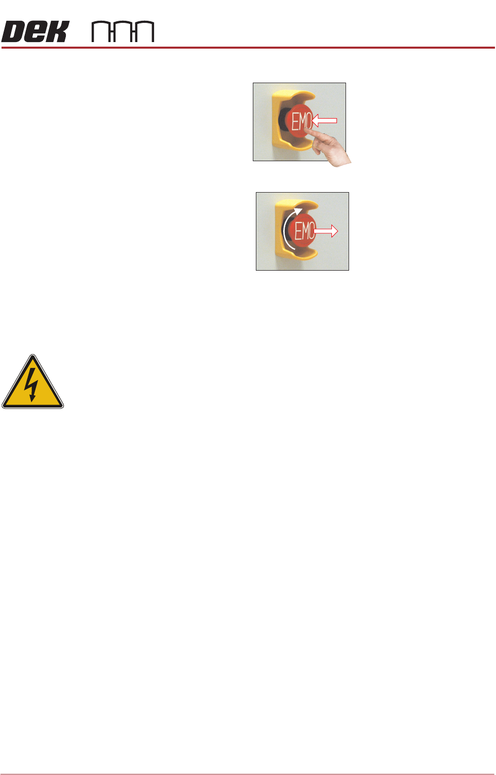
The EMO switch, once pressed, is a latching switch and requires resetting.
Recovery To reset the EMO, turn the button clockwise until it unlatches.
Press the Start button, to restore electrical and pneumatic power to the
machine. When prompted by a screen message press the System button.
Electrical Lockout
WARNING
LETHAL VOLTAGE. DANGEROUS VOLTAGES EXIST IN THIS EQUIPMENT.
ENSURE ALL ELECTRONIC COVERS AND MAIN MACHINE COVERS ARE
FITTED BEFORE OPERATING THIS EQUIPMENT.
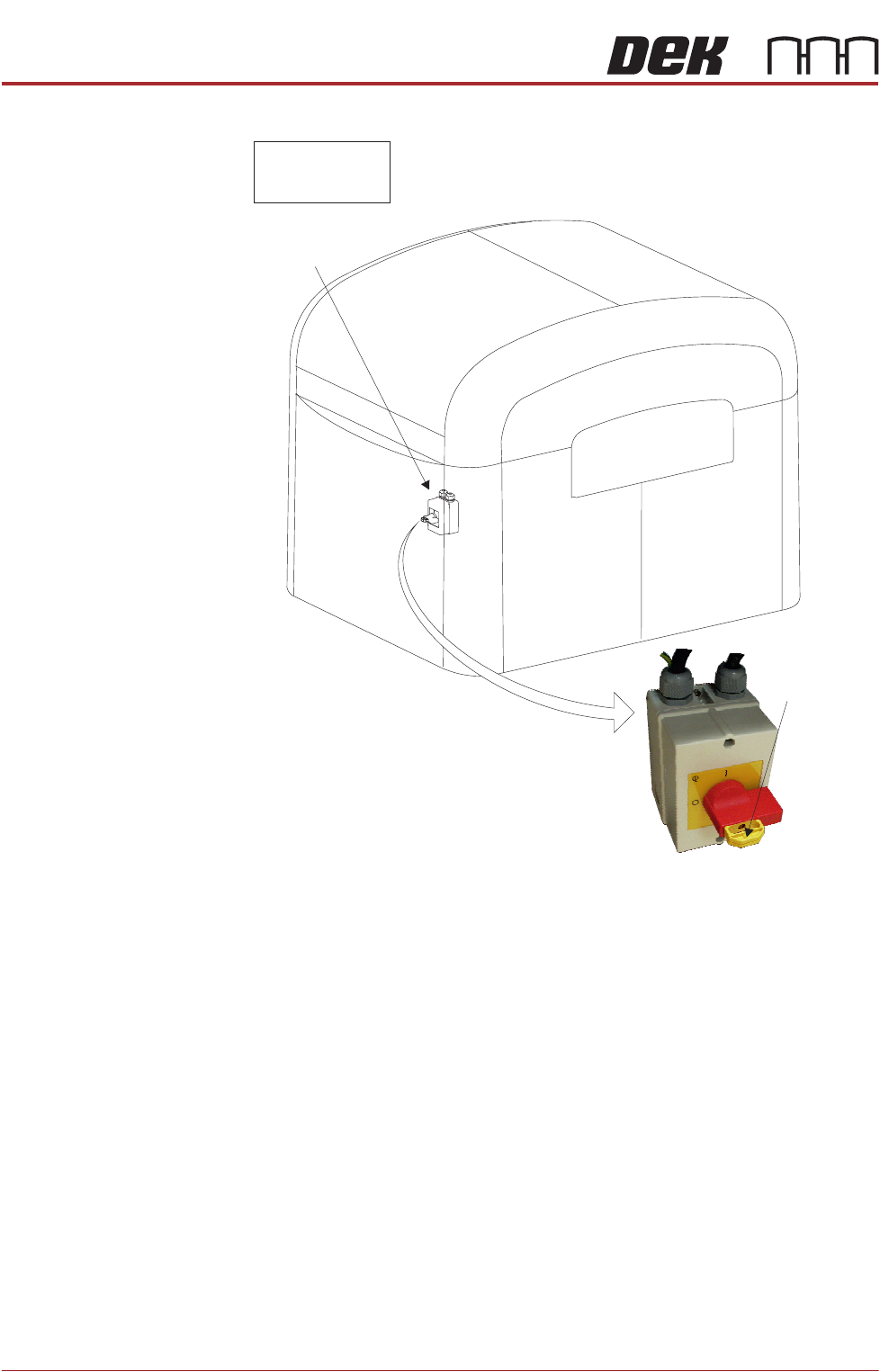
Electrical lockout of the machine is achieved by applying a padlock, or any other
suitable locking device, through the centre pull-out section of the mains isolator
switch. This can only be achieved when the switch is in the OFF position.
To electrically lockout the machine, carry out the following procedure:
1. Close down the machine software.
2. Switch the mains isolator to the OFF position.
3. Pull the yellow centre section of the mains isolator switch out.
4. Fit a padlock or suitable locking device through the lockout point in the
INSTALLATION APPENDIX
SAFETY FEATURES
2.6 Appendix to Micron Technical Manuals Chapter Issue 1 June 15
centre section of the switch.
5. This completes the electrical lockout.
Mains Isolator
Switch
NOTE
Switch shown in
the OFF position
View on Front of Machine
Lockout
Point

INSTALLATION APPENDIX
SAFETY FEATURES
Chapter Issue 1 June 15 Appendix to Micron Technical Manuals 2.7
Pneumatic Lockout
WARNING
COMPRESSED AIR. COMPRESSED AIR SHOULD NEVER IMPINGE UPON THE
BODY. PORTS, PIPES, ETC MUST NEVER BE BLOCKED BY HAND. BEFORE
CONNECTING OR DISCONNECTING ANY PNEUMATIC COMPONENTS, ENSURE
THE COMPRESSED AIR SUPPLY HAS BEEN DISSIPATED AND DISCONNECTED
FROM THE MACHINE.
Pneumatic lockout of the machine is achieved by:
NOTE
If the electrical lockout procedure has just been implemented, go to Step 3.
1. Close down the machine software.
2. Switch the electrical mains isolator to the OFF position.
3. Turn OFF and lockout the factory’s main pneumatic supply to the machine.
4. Pressurised air remaining in the pneumatic supply line is vented via the
pneumatic dump valve.
5. Raise the rear printhead cover.
6. Remove the rear panel and check the mains regulator gauge to confirm all
pressurised air has been vented.
7. Disconnect the pneumatic supply line from the machine.
8. This completes the pneumatic lockout.