222085 Issue 1 - Horizon APiX Appendix Manual.pdf - 第32页
INSTALLATION APPENDIX CENTRE OF GRAVITY AND SEISMIC ANCH ORAGE Chapter Issue 1 June 15 Appendix to Micron Technical Manuals 2.13 CENTRE OF GRA VITY AND SEISMIC ANCHORAGE Side View (right) Centre of Gravity a b c d h L1 L…

INSTALLATION APPENDIX
EXTERNAL SERVICES
2.12 Appendix to Micron Technical Manuals Chapter Issue 1 June 15
ASM requires additional machine supply protection with the fitment of an
external double pole circuit breaker conforming to national, federal or local
legislation. ASM recommends that the external circuit breaker is fitted near the
DEK printer and within easy reach of the operator. Use the following table to
ensure the recommended circuit breaker is used:
NOTE
An over current circuit breaker protects both the machine’s internal wiring and
components from overheating or catching fire during fault conditions. Under no
circumstances must a circuit breaker of value greater than 25 Amps be fitted.
Equipment If the equipment is used in a manner not specified by the manufacturer, the
protection provided by the equipment may be impaired.
This equipment should be used in accordance with the operating instructions.
ASM absolves itself of all responsibility if the machine is not used within its
operating envelope or for it’s intended purpose.
Voltage Value of Wall Mounted Circuit Breaker
(without Internal Vacuum Unit)
Value of Wall Mounted Circuit Breaker
(with Internal Vacuum Unit)
115V 10 Amp 25 Amp
230V 4/6 Amp 13/16 Amp
INSTALLATION APPENDIX
CENTRE OF GRAVITY AND SEISMIC ANCHORAGE
Chapter Issue 1 June 15 Appendix to Micron Technical Manuals 2.13
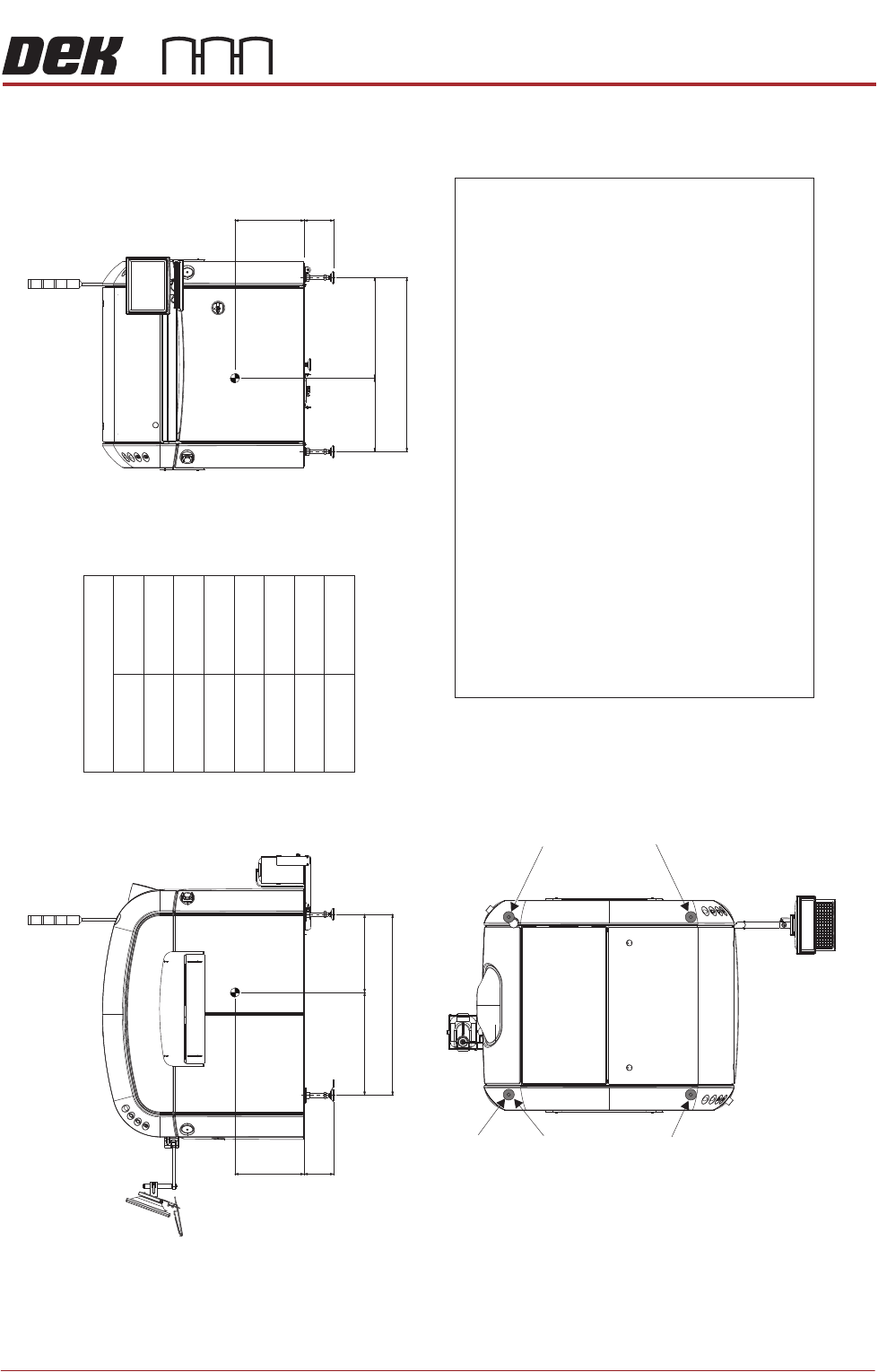
CENTRE OF GRAVITY AND SEISMIC ANCHORAGE
Side View (right)
Centre of Gravity
a
b
c
d
h
L1
L2
L3
188mm
440mm
Plan View
Centre of Gravity
Seismic Anchorage
Machine Feet
(in 4 positions)
Seismic Anchorage
The calculations for the downward and upward force of the feet
is calculated in line with the 1997 Uniform Building Code and
SEMI S2-0703. Results indicate that under worse circumstances
(calculation for hazardous fluids) an upward lifting force has to be
expected and it is strongly recommended to secure the machine
directly to the floor.
NOTE
In the figure on the left, negative numbers are upward loads and
positive numbers are downward loads.
Appropriate attachment points may be fitted to the front and rear
of the machine base frame. For more information, contact ASM
Assembly Systems Weymouth.
Alternatively, the supplied machine feet can be replaced with feet
incorporating holes allowing the feet to be secured directly to the floor.
Additional seismic calculations must be undertaken for the floor and
any anchor points that are used.
The length of the machine feet (measurement in the figures above)b
must not exceed 1 mm to meet seismic anchorage calculations.88
1106mm
466mm
654mm
640mm
496mm
1150mm
Front View
CG
L2
a
b
h
L1
CG
L3
d
b
h
c
Min = - kg63
Max = kg369
Min = - kg15
Max = kg435
Min = - kg48
Max = kg280
Min = - kg53
Max = kg372
INSTALLATION APPENDIX
MAINTENANCE TASK CLEARANCE
2.14 Appendix to Micron Technical Manuals Chapter Issue 1 June 15
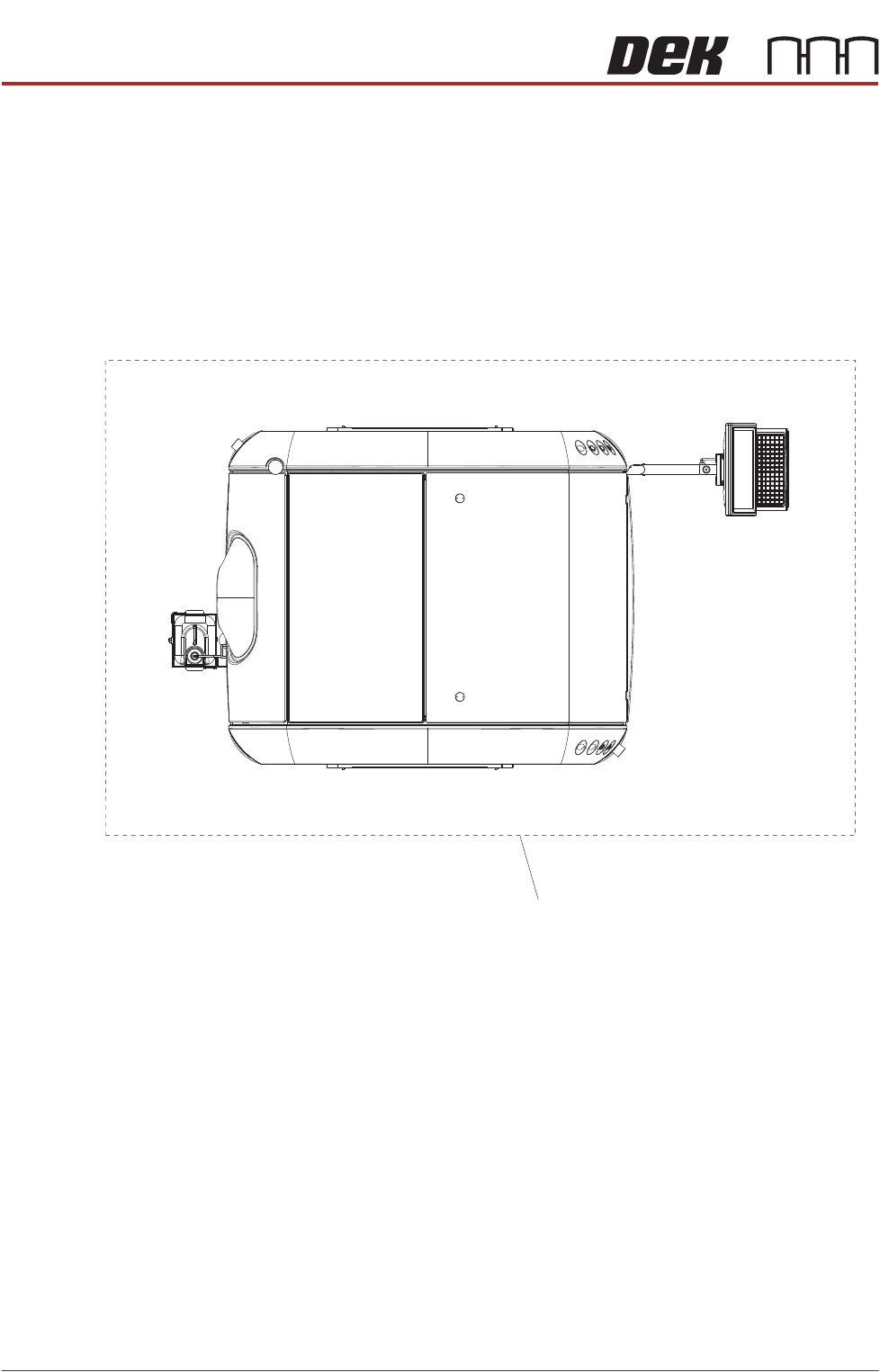
MAINTENANCE TASK CLEARANCE
Maintenance Task Clearance
For maintenance tasks SEMI S8-0712a recommends clearance
of at least 1.2m (48in.) from machine.
Maintenance Task
Clearance