222085 Issue 1 - Horizon APiX Appendix Manual.pdf - 第48页
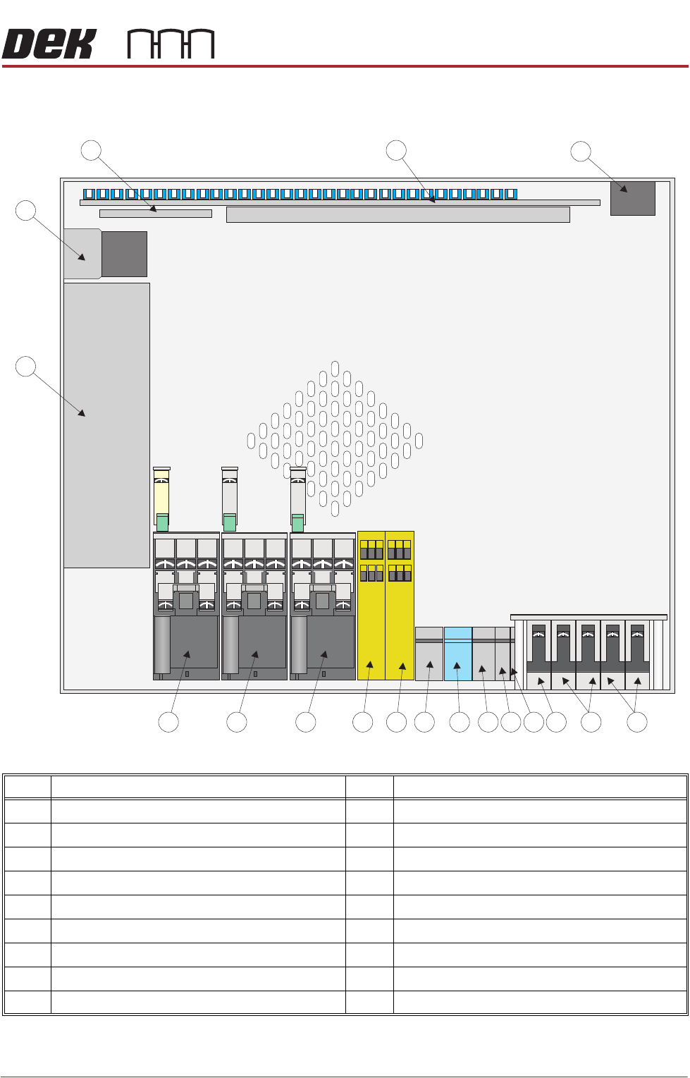
TECHNICAL REFERENCE APPENDIX M37 POWER SUPPLY ENCLOSURE Chapter Issue 1 June 15 Appendix to Micron Technical Manuals 3.11 M37 POWER SUPPL Y ENCLOSURE Figure 3-2 M37 Power Supp ly Enclosure Layout - Plan V iew Item Descri…
TECHNICAL REFERENCE APPENDIX
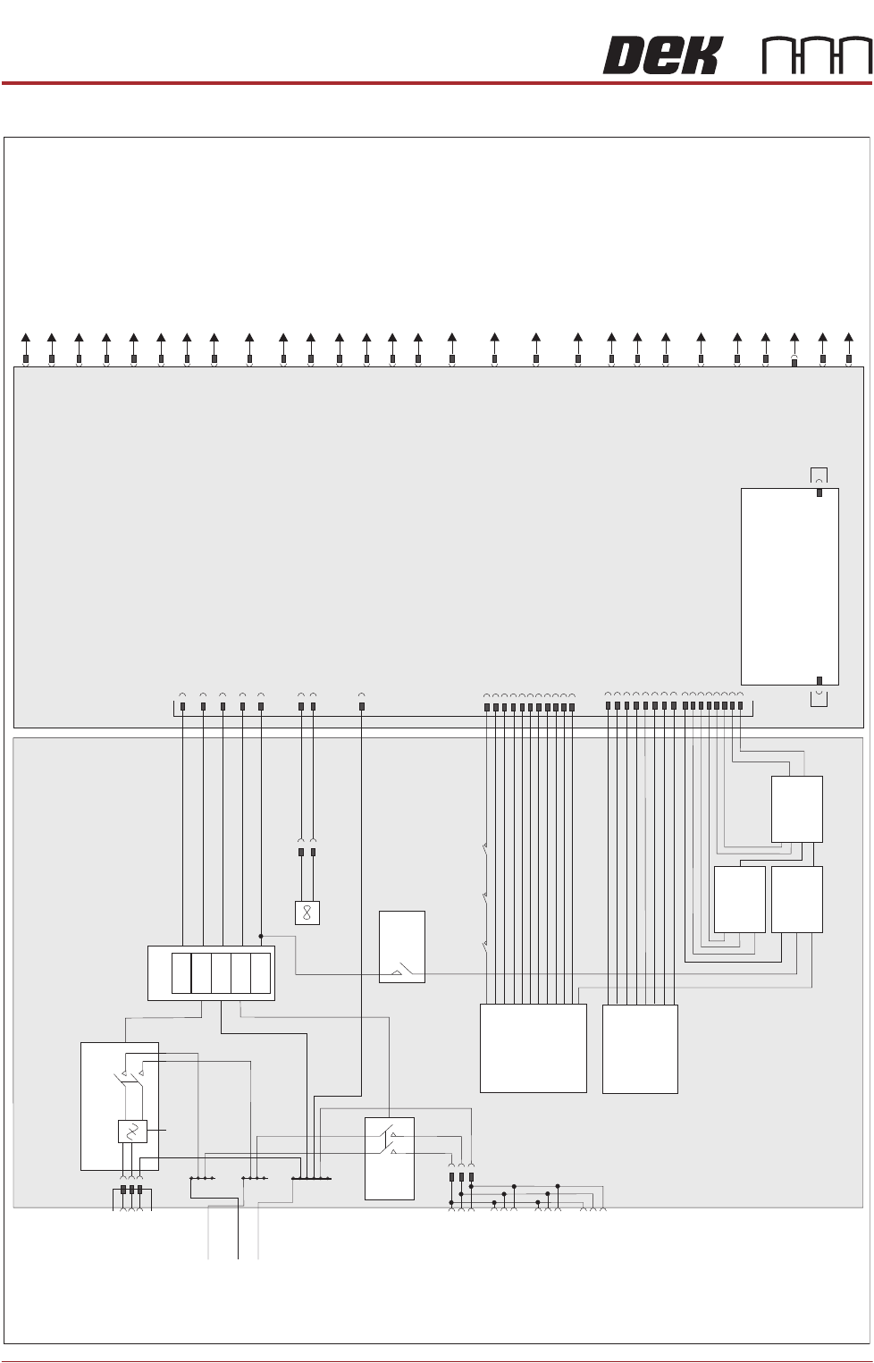
ELECTRICAL SCHEMATIC
3.10 Appendix to Micron Technical Manuals Chapter Issue 1 June 15
ELECTRICAL SCHEMATIC
M37 Power Supply Crate
CB 32
10A
PSU 1
+24V
-12V
+12V
+5.5V
+42V
Internal Vac Pump
CB34
16A
Filter
TB2
TB3
L
N
E
Mains Isolator
TB1
M37SK31
PC Supply
M37SK32
Monitor Supply
M37SK33
Spare
M37SK34
Spare
M37SK35
Internal Vac Supply
CB33
10A
2 Handed
Safety Relay
PIHZ X1
RL2
E Stop Relay
PNOZ X2
RL1
M37TB01
Power Distribution PCB
M37SK36
Part
CON1
Part
CON2
Part
CON3
CON 1
CON 3
CON 2
Fan
PSU Monitor Board
M37PL28
M37PL29
MMI
M37SK27
Safety I/O
M37PL26
M37SK24
E Stop Blanking Plug
M37SK30
USB Port
M37SK23
Rear Cover Interlock -
Interlock Blanking Plug
M37SK22
Front Cover Interlock
M37SK21
Spare Servo Motor Power
M37SK20
RTC I/O Node 11
M37SK19
Camera Y I/O Node 9
Servo Motor Power
M37SK18
Camera X I/O Node 8
Servo Motor Power
SpareM37SK01
Rising Table I/O Node 6
Servo Motor Power
M37SK16
M37SK17
Print Carriage I/O Node 7
Servo Motor Power
Low Current DCM37SK02
High Current DC
M37SK03
Machine I/O Node 2
M37SK04
Print Carriage I/O Node 3
M37SK05
USC I/O Node 4
M37SK06
Not Used
M37SK07
Paste Dispense I/O Node 10
M37SK08
HTC M27 - RTC I/O Node 12 -
Dual Lane I/O Node 15
M37SK09
Grid-LokM37SK10
Internal Lighting & Ionizer
M37SK11
+12V Spare
M37SK12
Remote Barcode Reader
M37SK13
Hand Held Barcode Reader
M37SK14
Machine Fans
M37SK15
M37SK25
E Stop Buttons
TECHNICAL REFERENCE APPENDIX
M37 POWER SUPPLY ENCLOSURE
Chapter Issue 1 June 15 Appendix to Micron Technical Manuals 3.11
M37 POWER SUPPLY ENCLOSURE
Figure 3-2 M37 Power Supply Enclosure Layout - Plan View
Item Description Item Description
1 Mains Power Output Sockets 10 2 Handed Safety Relay
2 Circuit Breaker CB34 11 E Stop Relay
3 Circuit Breaker CB33 12 Contactor Con 1
4 Circuit Breaker CB32 13 Contactor Con 2
5 Terminal Block TB5 14 Contactor Con 3
6 Terminal Block TB4 15 Power Supply Unit PSU
7 Terminal Block TB3 16 Internal Vacuum Pump Mains Filter
8 Terminal Block TB2 17 PSU Monitor Board
9 Terminal Block TB1 18 Power Distribution PCB
1
2
3
4
5
678
910
11
12
1817
16
15
1314
TECHNICAL REFERENCE APPENDIX
M37 POWER SUPPLY ENCLOSURE
3.12 Appendix to Micron Technical Manuals Chapter Issue 1 June 15
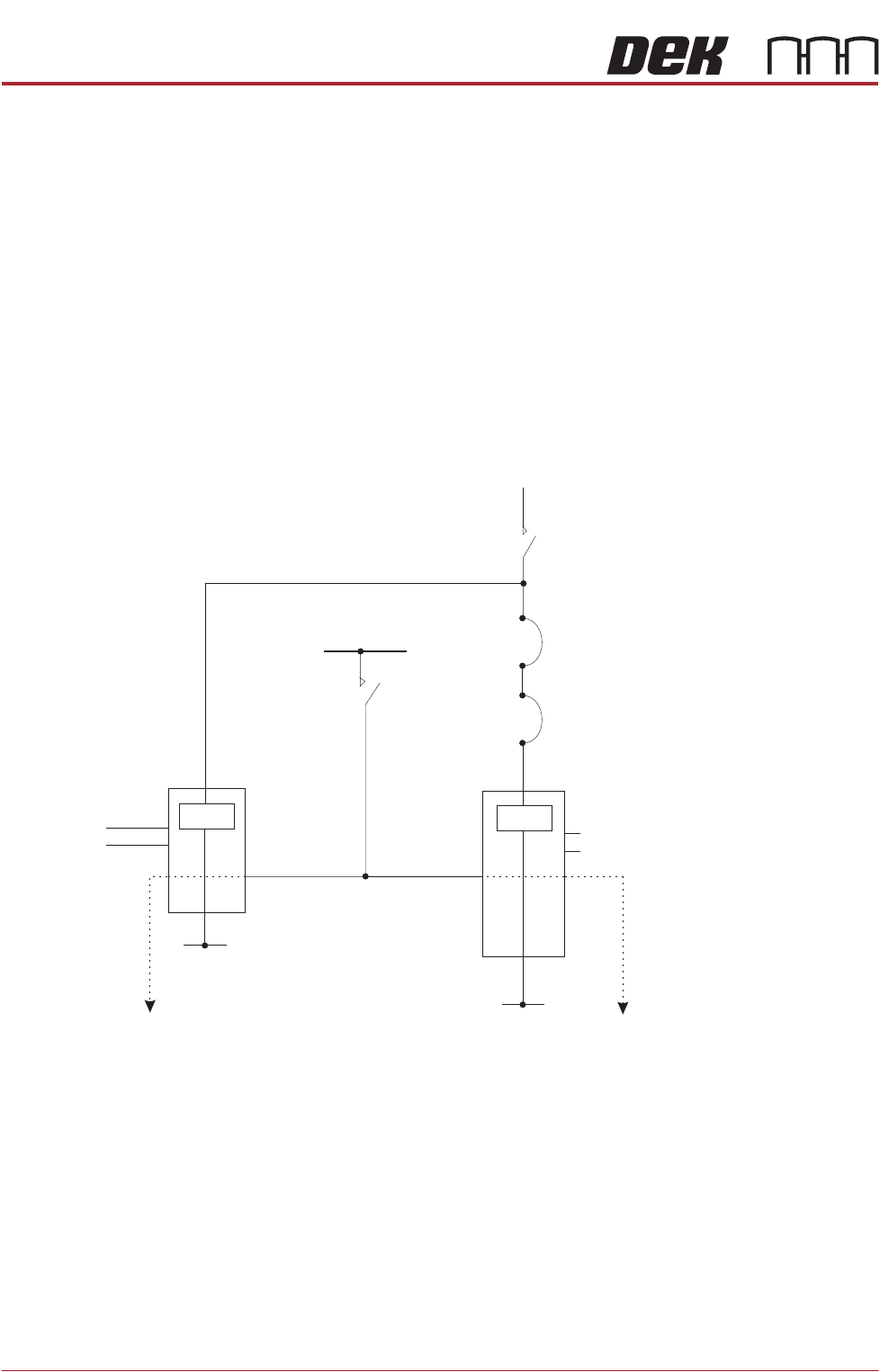
Printhead Cover
Loop Components
The printhead cover loop circuit comprises the following:
• The E Stop Relay
• The Two-Handed Relay
• System Switch
• Front Cover Interlock Switch
• Rear Cover Interlock Blanking Plug
• Printhead Cover Loop Circuit
• E Stop Blanking Plug (in 2 positions)
• Jog Buttons
Figure 3-3 Simplified Printhead Cover Loop Circuit
CON 1 CON 2 CON 3 Sys. Switch
AUX AUX AUX
E Stop
Relay
0V
E Stop Blanking Plug
E Stop Loop Supply
(Software E Stop)
Contactors
1, 2 & 3
Supplies 24V SW and 42V dc to the motors
Front Cover Interlock
CB1
3.15A
24V US
2 Handed
Relay
0V
Contactors
1 & 3
Jog
Buttons
Supplies 24V SW to the motors
Rear Cover Interlock/