222085 Issue 1 - Horizon APiX Appendix Manual.pdf - 第79页
TECHNICAL REFERENCE APPENDIX CALIBRATIONS 3.42 Appendix to Micron Technical Manuals Chapter Issue 1 June 15 Associated Calibrations Figure 3-6 Associated Calibrations NOTE For information on the T est Cycles function see…

TECHNICAL REFERENCE APPENDIX
CALIBRATIONS
Chapter Issue 1 June 15 Appendix to Micron Technical Manuals 3.41
28. Select Step, the camera moves to the third screen fiducial. Position the
fiducial centrally with the box as previously described.
29. Select Step, the camera returns to the home position and the rising table
moves to the print height position.
30. Select Step, the print carriage moves to the rear position.
31. Open the front printhead cover.
32. Apply paste to all 25 positions on the screen.
33. Close the front printhead cover.
34. Press the System button.
35. Select Step.
36. Select Step.
37. Select Accept, the table drops and the camera moves to the first fiducial.
38. Select Brd Fid Setup and carry out Fiducial Setup procedure as described
in Appendix A - Vision System Set Up.
39. If any changes have been made, select Learn Fiducial. If no changes have
been made, select Locate Fiducial.
40. Select Exit.
41. Select Scrn Fid Setup and carry out Fiducial Setup procedure as described
in Appendix A - Vision System Set Up.
42. If any changes have been made, select Learn Fiducial. If no changes have
been made, select Locate Fiducial.
43. Select Exit.
44. Select Step, the Offset results are displayed.
45. Select Single, the camera moves to each of the 24 remaining fiducial
positions in turn.
46. Select Auto Board, the board data file is saved.
47. Remove the board from the transport rails.
48. Select Exit.
49. Select Back.
NOTE
ASM recommends that the calibration screen is cleaned with Isopropyl Alcohol
(IPA) impregnated lint free wipe on completion of the offset calibration.
If for any reason the camera cannot locate the board or screen fiducial (except
for poor prints), select Fiducial Setup and relearn the fiducial, (refer to Appen-
dix A - Vision System Set Up for details on setting up the fiducial recognition
strategy).
Select Retry, the sequence continues and does not have any detrimental effect
to the calibration.
TECHNICAL REFERENCE APPENDIX
CALIBRATIONS
3.42 Appendix to Micron Technical Manuals Chapter Issue 1 June 15
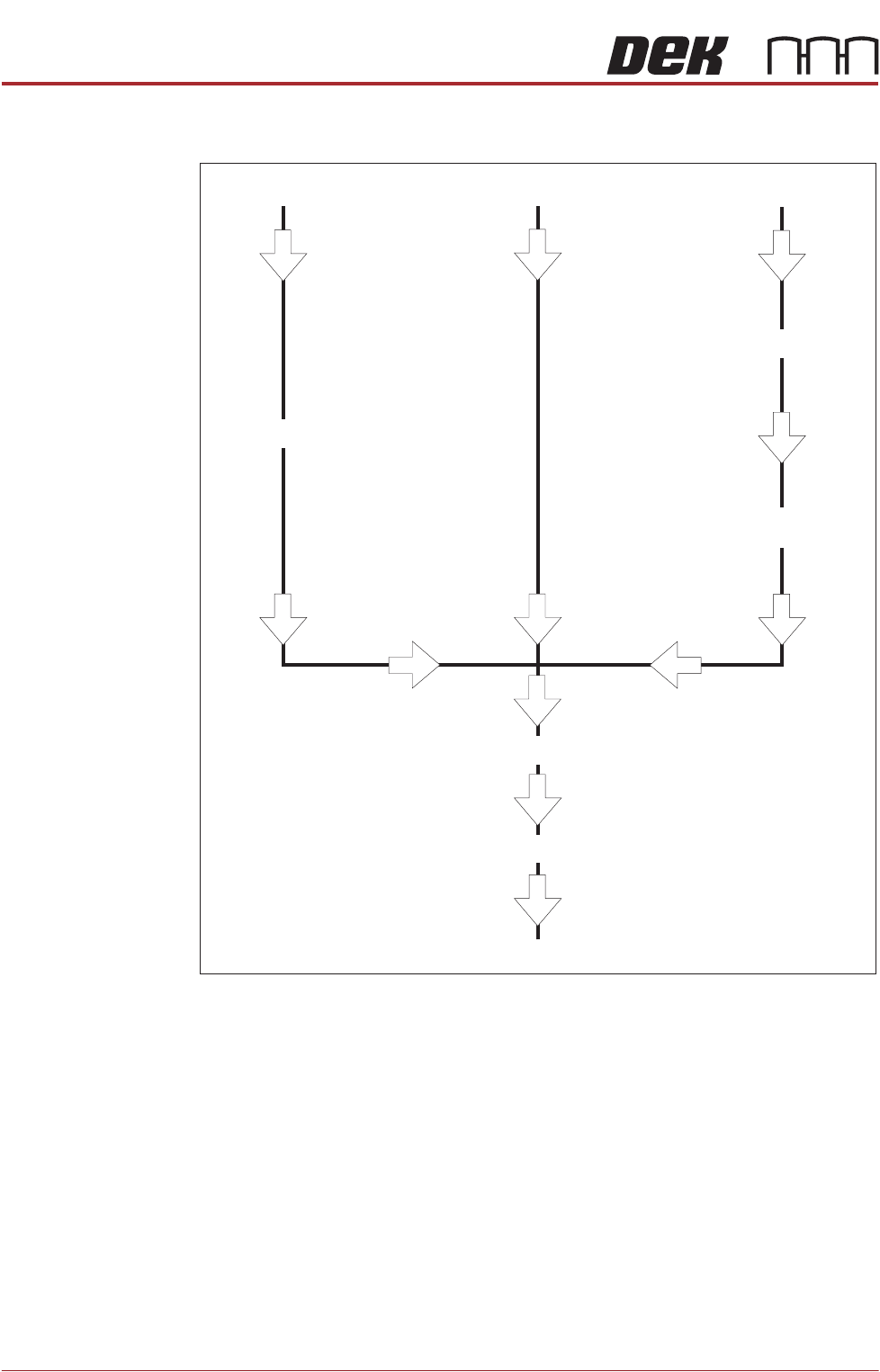
Associated Calibrations
Figure 3-6 Associated Calibrations
NOTE
For information on the Test Cycles function see the Screen Alignment Chapter.
Camera Replacement
Motor Replacement
Offset Calibration
Belt Replacement
Vision Height
Belt Tension
Camera Reference Position
VisionCalibration
X Axis to Front Rail
Parallelism
TECHNICAL REFERENCE APPENDIX
CALIBRATIONS
Chapter Issue 1 June 15 Appendix to Micron Technical Manuals 3.43
Transport Rails
NOTE
Where the printer is connected to inline equipment make sure that the FMI
functionality is turned OFF before proceeding.
The front and rear board transport belts are driven independently by two
variable speed motors. Inevitably one motor drives faster than the other motor.
It is necessary to calibrate these motors so that they drive at the same speed.
Feeder motor speed is measured using a tachometer on the input or output
pulley and adjusted by a potentiometer control on each motor.
Calibration
Procedure
1. Remove the right hand side safety cover to gain access to the transport belt
motors.
2. Select Maintenance.
3. Select Diagnostics.
4. Use Next or Previous to highlight Rail System.
5. Select Select Module.
6. Use Next or Previous to highlight Belt Speed Calibration.
7. Select Run Diagnost.
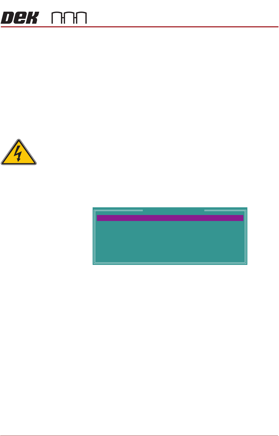
The following window is displayed:
NOTE
Belt Speed Calibration figures displayed on this page have no relevance to
the belt speeds on the machine.
8. Select Front L 2 R Speed.
9. Select Incr. or Decr. to start the belts
SEMI 2
Belt Speed Calibration
64
64
64
64
64
64
64
64
FRONT L 2 R SPEED
FRONTR 2 L SPEED
REAR R 2 L SPEED
REAR R 2 L SPEED
FRONT L 2 RALT SPEED
FRONTR 2 L ALT SPEED
REAR L 2 RALT SPEED
REAR R 2 L ALT SPEED