TR7600 SIII_Operation_en_v_2_0_2 - 第11页
Test Research, Inc . TR7600 SIII Series User Gu ide – Operat ion 3 1.3 TRI Application Basic Automatic X-Ray Ins pection w ill be conducted wit h the f ollowing 3 applications. 1) TR7600: A XI main software wher e m ajor…
Test Research, Inc.
2 TR7600 SIII Series User Guide – Operation
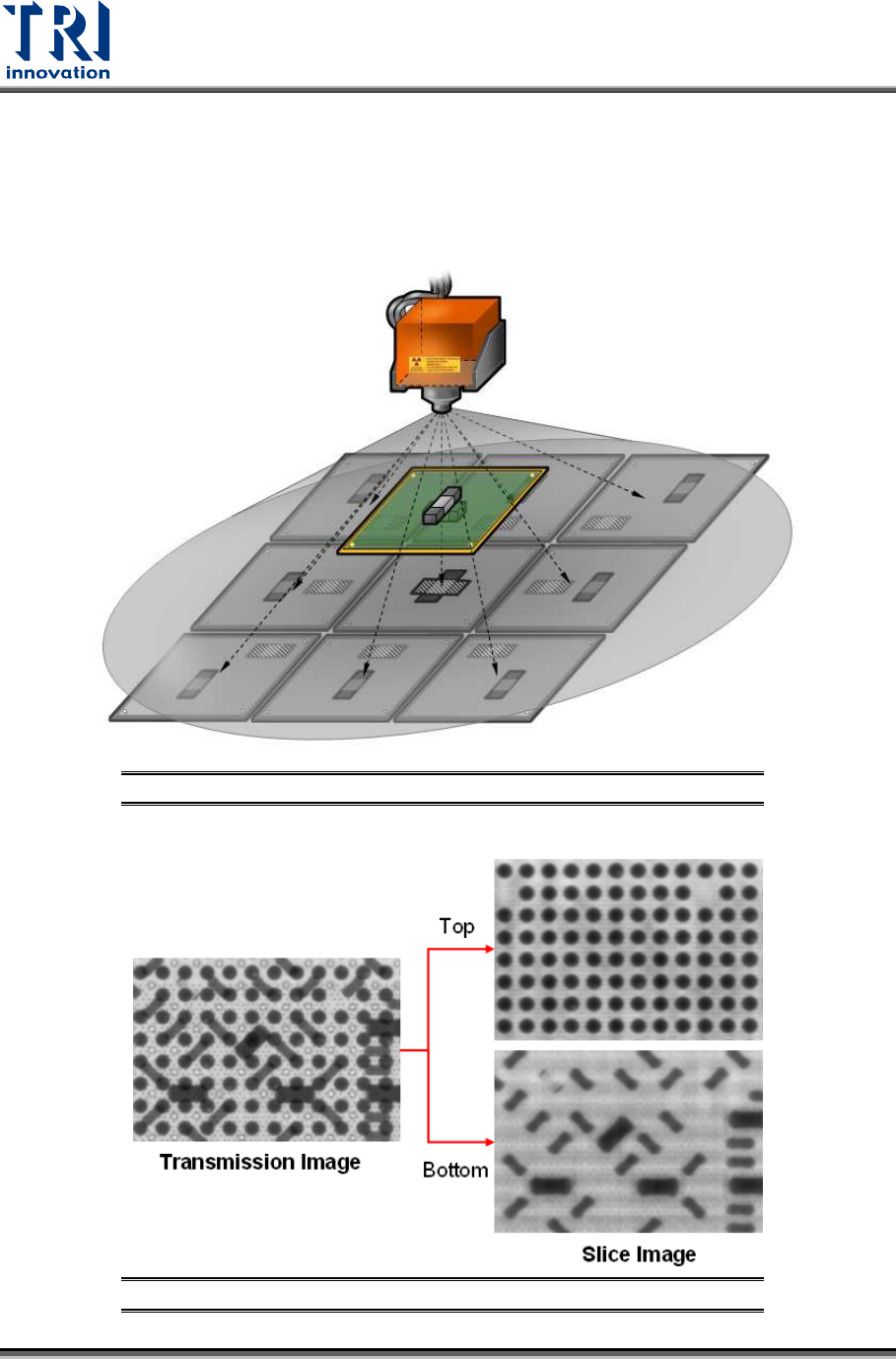
1.2 Basic Principles
Refer to the Figure below. The six-axis system is able to capture images using different
resolutions and angles. The machine could capture nine images with different angles,
separate the overlapping top and bottom images and combine all images to become one
image as you see on the screen.
Figure 2: Slicing with Planar Motion
Figure 3: Transmission & Slice Images

Test Research, Inc.
TR7600 SIII Series User Guide – Operation 3
1.3 TRI Application
Basic Automatic X-Ray Inspection will be conducted with the following 3 applications.
1) TR7600: AXI main software where major PCB inspections are programmed and
conducted
2) TRI AXI InsertData: Transport and categorize the files into designated folders.
3) TRI AXI RS: Repair Station main software where user can confirm the defects and
retrieve the inspection data here.
Test Research, Inc.
4 TR7600 SIII Series User Guide – Operation
2 M
ACHINE
O
PERATION
2.1 Safety Control
Start-up Protection: For safety purposes, after you turn on a machine, the X-Y Table will
not start immediately. You have to ensure the machine and environment are safe first
and then press the [Reset] button on the human-computer interface to initialize the X-Y
Table system.
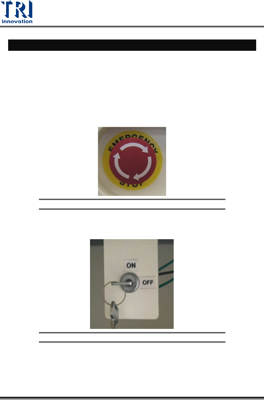
Emergency stop: If there is an emergency, press this stop button to stop the machine.
When safe, turn the emergency stop clockwise to release the button and select [Reset]
on the human-computer interface to reset the machine to normal status.
Figure 4: Emergency Stop
Safety Interlock: The safety interlock is located at the right hand side inside the front door.
When it is switched to [ON], the movement of machine will be stopped as the front or
rear door is open; if it is switched to [OFF], the safety device is disabled.
Figure 5: Safety Inter Lock
Operator Location: The optimal location for the operator is in front of the
monitor. Approximately 40-74cm away from the screen for a proper position to
view the machine monitor. And more than 5cm from equipment surface.
Please follow the safety instructions and warnings for a safer use of the
machine.