TR7600 SIII_Operation_en_v_2_0_2 - 第8页
Test Research, Inc. ii TR7600 SIII Ser ies User G uide – Op eration Figures Figure 1: Hardware Structure ..... ...... ..... ...... ..... ...... ..... ...... ..... ...... .... ...... ..... ..... ...... ..... ...... 1 Figu…

Test Research, Inc.
TR7600 SIII Series User Guide – Operation i
Contents
1
H
ARDWARE
S
TRUCTURE AND
B
ASIC
P
RINCIPLES
_______________________ 1
1.1 Hardware Structure ............................................................................................ 1
1.2 Basic Principles .................................................................................................. 2
1.3 TRI Application ................................................................................................... 3
2
M
ACHINE
O
PERATION
___________________________________________ 4
2.1 Safety Control ..................................................................................................... 4
2.2 Turning On the Machine ..................................................................................... 5
2.3 Start the Inspection Software ............................................................................. 6
2.4 Start to Inspect.................................................................................................... 8
2.5 Inspect the Same Module on other Same Type Machine ............................... 10
2.6 End Inspection .................................................................................................. 10
2.7 Other Settings ................................................................................................... 11
2.7.1 Enable Barcode Reader .................................................................. 11
2.7.2 Link to Repair Station and MES ...................................................... 13
3
R
EPAIR
S
TATION
C
ONFIRMATION
__________________________________ 15
3.1 Confirm Inspection Data ................................................................................... 15
3.2 Report Generation ............................................................................................ 17

Test Research, Inc.
ii TR7600 SIII Series User Guide – Operation
Figures
Figure 1: Hardware Structure ............................................................................................ 1
Figure 2: Slicing with Planar Motion ................................................................................. 2
Figure 3: Transmission & Slice Images ............................................................................ 2
Figure 4: Emergency Stop ................................................................................................ 4
Figure 5: Safety Inter Lock ................................................................................................ 4
Figure 6: Breaker ............................................................................................................... 5
Figure 7: Shortcut of Software .......................................................................................... 6
Figure 8: Login Dialog Box ................................................................................................ 6
Figure 9: Open an Inspection Project ............................................................................... 6
Figure 10: VPLC Board In/Out Direction .......................................................................... 7
Figure 11: Set Conveyor Width ......................................................................................... 7
Figure 12: Inspection Mode .............................................................................................. 8
Figure 13: “Start” Button .................................................................................................... 8
Figure 14: “Start Test” Button ........................................................................................... 9
Figure 15: “Fail” Button ..................................................................................................... 9
Figure 16: Auto, Confirm or Offline Fine Tuning Modes ................................................... 9
Figure 17: Enable Barcode ............................................................................................. 11
Figure 18: Barcode Setting ............................................................................................. 12
Figure 19: Enable Repair Station and MES .................................................................... 13
Figure 20: Set Repair Station Path ................................................................................. 14
Figure 21: TRI AXI Repair Station .................................................................................. 15
Figure 22: Confirm Mode ................................................................................................ 15
Figure 23: Query Data by Auto, In-line or Barcode ........................................................ 15
Figure 24: Query Data by Offline Mode .......................................................................... 16
Figure 25: SPC Mode ...................................................................................................... 17
Figure 26: Defect Image and Simple Charts Display ..................................................... 17
Figure 27: Cumulative Changes of Desired Components .............................................. 18
Test Research, Inc.
TR7600 SIII Series User Guide – Operation 1
1 HARDWARE STRUCTURE AND BASIC PRINCIPLES
TR7600 SIII in-line Automated X-ray Inspection system uses X-ray technology to inspect
PCBAs and components. This system is ideal for inspecting BGA components and areas not
accessible by other test technology. Currently, the system could use 7µm, 10 µm, 15 µm and
20 µm resolution to perform inspection.
TRI proprietary image evaluation technology appraises the dark and light areas, separates
the different image slices and calculates the different slice heights during inspection.
Inspection result can be sent to Repair Station for analysis and follow up action.
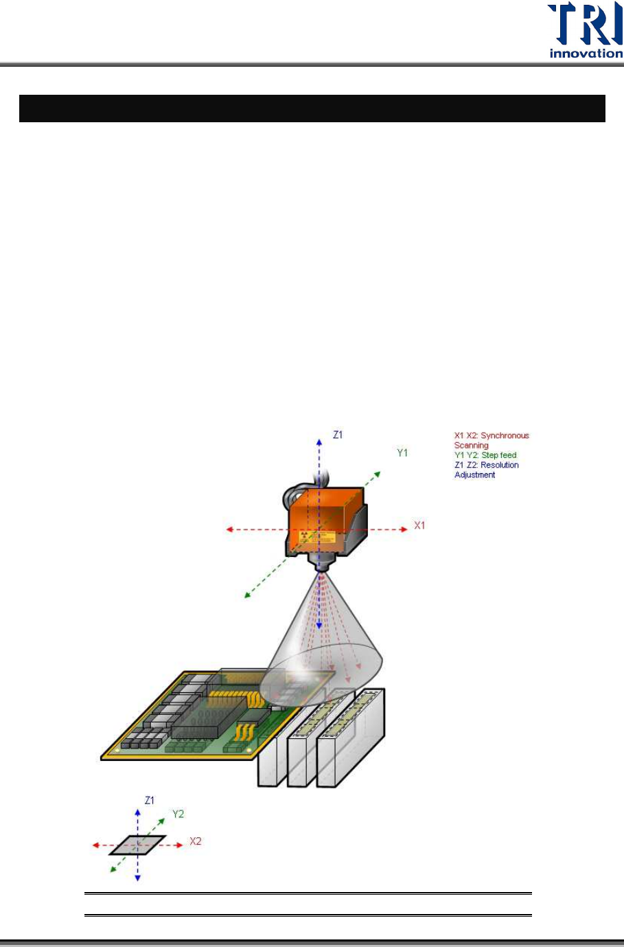
1.1 Hardware Structure
Refer to the Figure below. At the top of the system is X–ray source. It is moved by X-Y-Z
table system. At the center, the PCBA panel is transferred by conveyor and fixed by the step
motor and mechanism; at the bottom are cameras. The camera system is moved by X-Y-Z
table system in sync with the X–ray source. Images can be captured using nine different
angles.
Figure 1: Hardware Structure