SIPLACE D4i 规格说明书英文版 - 第11页
11 Placement Head Standard Functions / Options 12-nozzle Collect & Pl ace head S tandard functions Camera, vacuum sensor , force measurement, PCB war- page, check, individual re cording for each component Options Hig…
10
Placement Head
Overview
With the SIPLACE D4i, we
can provide you with an
extremely powerful place-
ment machine with four gan-
tries and four 12-nozzle
Collect&Place heads. It is
thus a high-speed placement
machine that combines a
high placement rate with
placement accuracy and
flexibility.
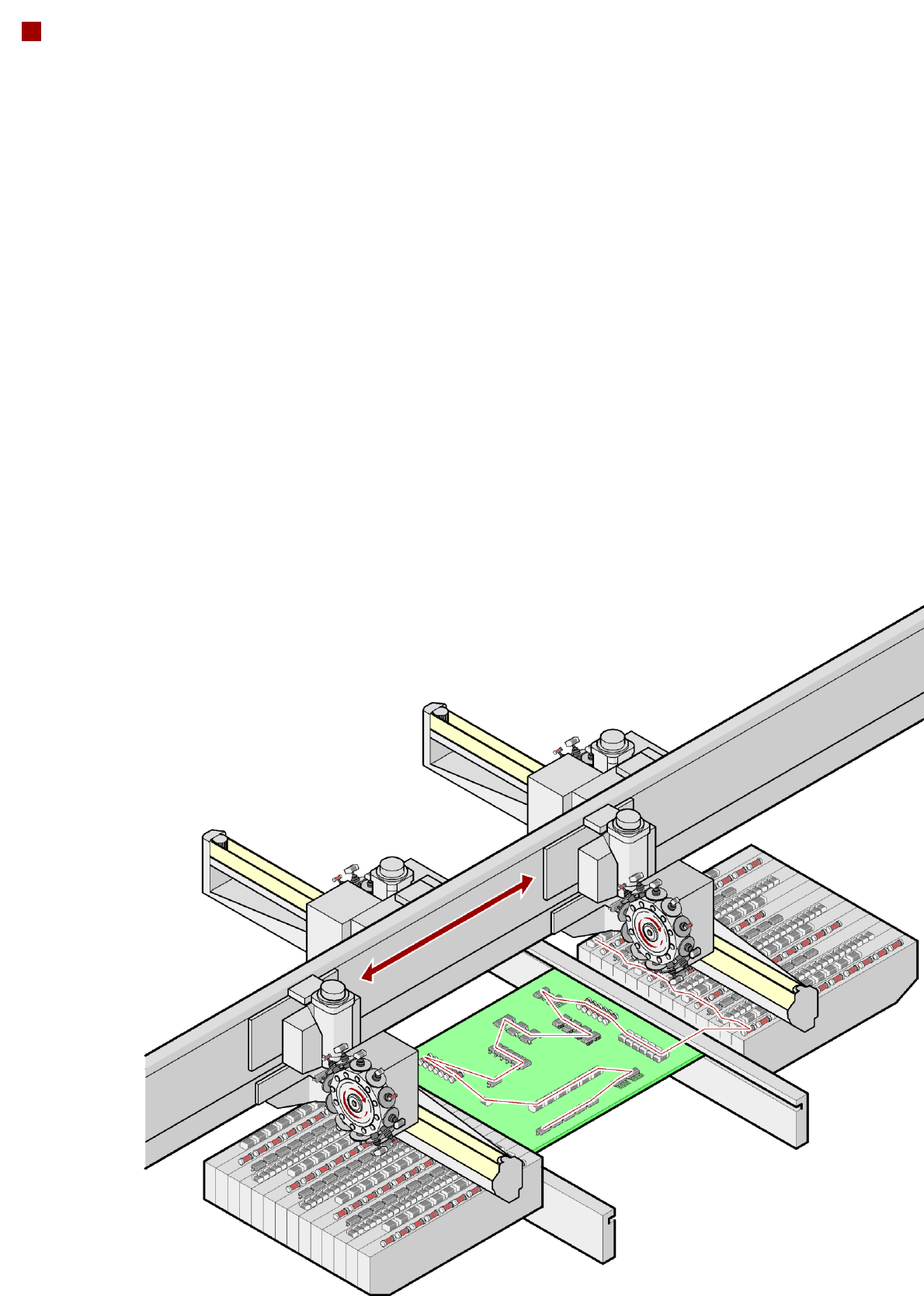
Collect&Place principle
The SIPLACE 12-nozzle
Collect & Place head works
on the Collect & Place princi-
ple. This means that, within
each cycle, 12 components
are picked up and "collected"
by the placement head, are
optically centered on the way
to the board and are rotated
into the required placement
angle. They are then placed
gently and accurately on the
PCB. This principle is partic-
ularly suitable for the high-
speed placement of standard
components.
Checking and self-learning
functions
The SIPLACE placement
heads' reliability can be fur-
ther increased with various
checking and self-learning
functions.
• Component sensor
It checks for the presence
of a component at the
nozzle before and after the
pick-up and placement
process.
• Digital camera on the
placement head
Checks the position of
each component at the
nozzle.
Any deviations from the
required pick-up position
are corrected before
placement takes place.
• Force sensor
Monitors the specified
component set-down
forces. With the sensor
stop method, differences
in height during pick-up
and any unevenness of
the PCB surface are com-
pensated during place-
ment.
• Vacuum sensor
Checks whether the com-
ponent was picked up or
set down correctly.
Collect&Place principle

11
Placement Head
Standard Functions / Options
12-nozzle Collect&Place head
Standard functions Camera, vacuum sensor, force measurement, PCB war-
page, check, individual recording for each component
Options High-resolution camera, component sensor, short nozzle,
short sleeve, nozzle changers, special nozzles
12
Placement Head
Technical Data
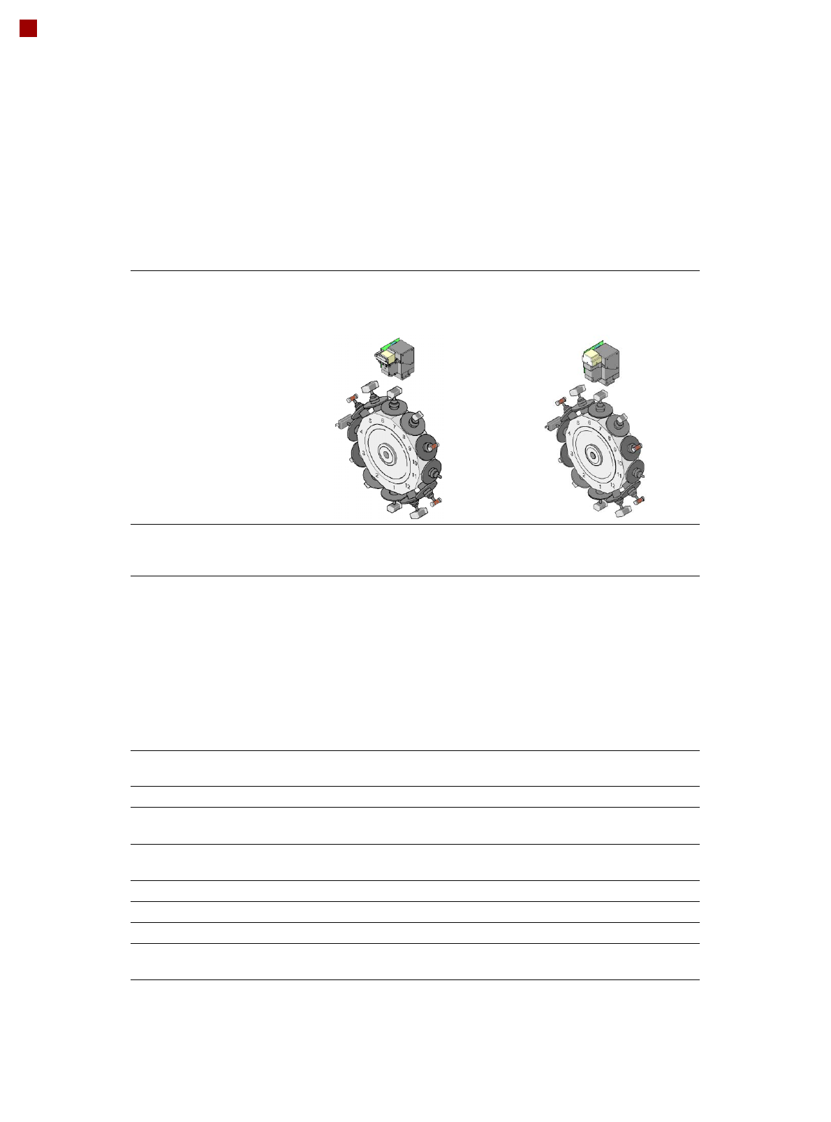
12-nozzle
Collect&Place head
CO camera type 28
12-nozzle
Collect&Place head
CO camera type 30
Component range
a
a) Please note that the range of components that can be placed is also affected by the pad geometry,
customer-specific standards, component packaging tolerances and component tolerances
0402 to PLCC44, BGA, µBGA, flip-
chip, TSOP, QFP, SO to SO32,
DRAM
01005
b
to flip-chip, bare die,
PLCC44, BGA, µBGA, TSOP, QFP,
SO to SO32, DRAM
b) With 01005 package
Component specification
max. height
min. lead pitch
min. lead width
min. ball pitch
min. ball diameter
min. dimensions
max. dimensions
max. weight
6 mm
0.5 mm
0.2 mm
0.35 mm
0.2 mm
1.0 x 0.5 mm²
18.7 x 18.7 mm²
2 g
6 mm
0.3 mm
0.15 mm
0.25 mm
0.14 mm
0.4 x 0.2 mm²
18.7 x 18.7 mm²
2 g
Programmable set-down
force
2.4 N - 5.0 N 2.4 N - 5.0 N
Nozzle types 9xx 9xx
X/Y accuracy
c
c) The accuracy value was measured using the vendor-neutral IPC standard
± 50 µm/3σ
± 67 µm/4σ
± 50 µm/3σ
± 67 µm/4σ
Angular accuracy ± 0.53°/3σ
± 0.71°/4σ
± 0.53°/3σ
± 0.71°/4σ
Component range 98% 98.5%
Component camera type 28 30
Illumination levels 5 5
Possible illumination level
settings
256
5
256
5