SIPLACE D4i 规格说明书英文版 - 第14页
14 PCB Conveyor Overview Conveyor principle If the board has reache d the placement area and pa ssed a light barrier , it is braked. An additional las er light bar rier determines the position of the board. As soon as th…
13
Placement Head
Nozzle Changer
Technical data
Dimensions
(length x width x height) 472.5 x 63 x 77 mm³
Number of magazines min. 1 / max. 5,
each with 12 nozzle
holders
Nozzle types 9xx
Compressed air connection 0.48 MPa (4.8 bar)
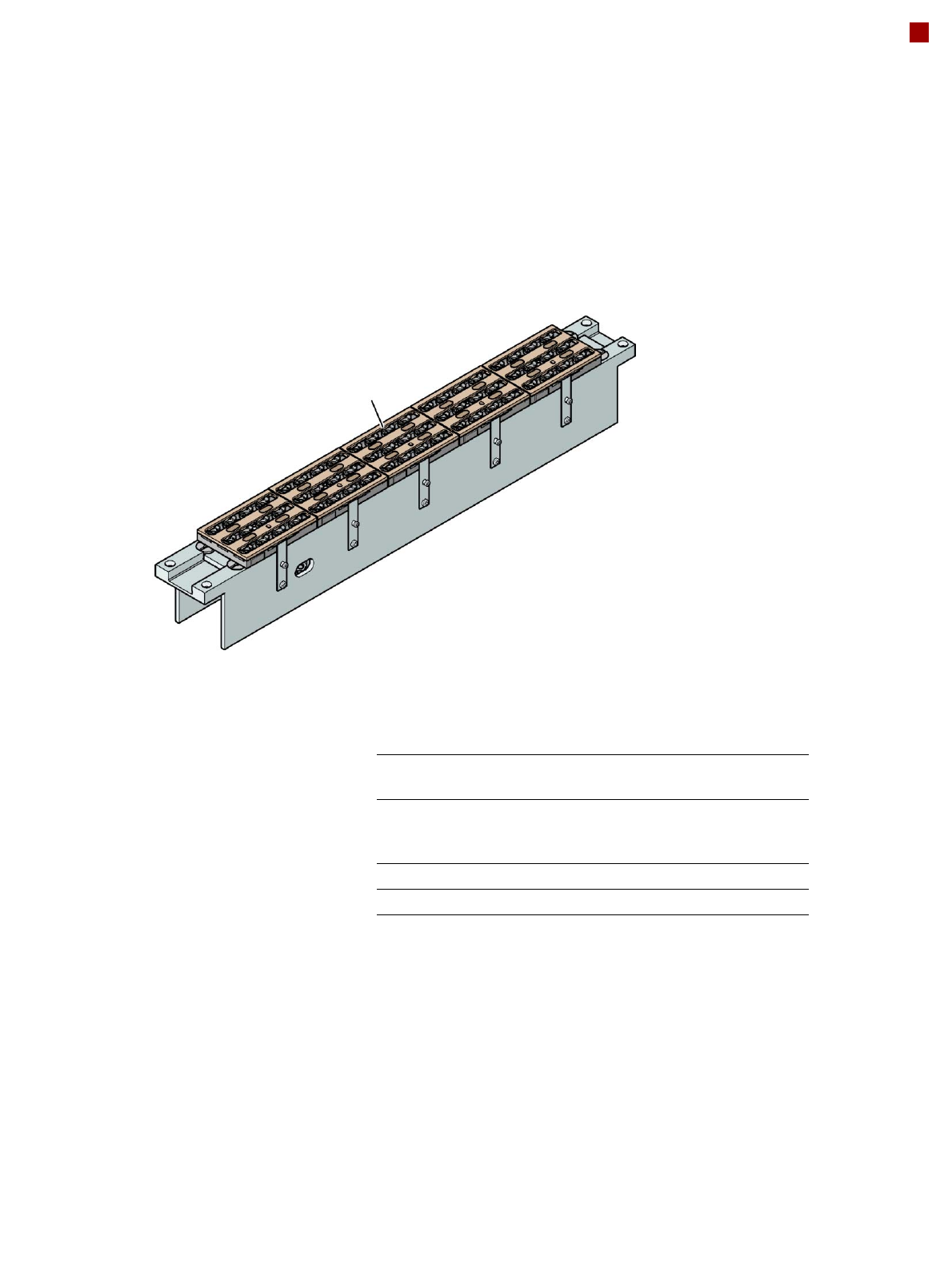
Nozzle changer for the 12-nozzle Collect&Place head
(5 magazines
→ 60 nozzle holders in total)
Magazine for 12
type 9xx nozzles
Description
Nozzle changers increase
the flexibility of placement
heads when processing dif-
ferent components. The noz-
zle configuration can be
quickly modified for new
placement jobs. Exactly
defined positions and the per-
fect seating of the nozzle in
the garage guarantee mini-
mal radial eccentricity at the
placement head.
Up to eight nozzle changers
may be installed on the
SIPLACE D4i machine as an
option.
14
PCB Conveyor
Overview
Conveyor principle
If the board has reached the
placement area and passed
a light barrier, it is braked. An
additional laser light barrier
determines the position of
the board. As soon as the
circuit board has reached its
target position, the conveyor
belt is stopped and the board
is clamped from below. The
placement process then
starts immediately. Move-
ment and clamping of the
PCBs are monitored.
The conveyor can be easily
matched to many different
PCB widths by the automatic
electrical width adjustment.
The fixed conveyor rail may
be located on the left or right
for both the flexible dual con-
veyor and the single con-
veyor.
Single conveyor
On the single conveyor,
PCBs are moved one after
the other into the placement
machine and placed on a
conveyor track.
Flexible dual conveyor
To keep the range of PCBs to
be processed as wide as
possible - whilst maintaining
maximum productivity - the
flexible SIPLACE dual con-
veyor allows you to choose
between single conveyor
mode and dual conveyor
mode.
In dual conveyor mode, two
PCBs are moved into the
placement machine and
placed either simultaneously
(synchronous operation) or
alternately (asynchronous
operation).
In synchronous mode, two
PCBs are moved into the
placement position at the
same time. They are pro-
cessed as a common panel.
This allows the top and bot-
tom of PCB to be processed
on the same line and, for
products with very different
components to be placed,
the common optimization of
all the components to be
placed on both PCBs makes
it possible to increase output.
In asynchronous mode,
only one PCB in a transport
track is processed. At the
same time, another PCB in
the second transport track is
moved into the placement
position. This saves the full
conveying time of one PCB,
thus considerably increasing
performance, particularly for
PCBs with a short cycle time.
The placement process
starts as soon as one PCB is
transported into the process-
ing area.
Conveyor buffer
SIPLACE PCB conveyors
have buffer zones. If shorter
waiting times occur in a
placement area (due to lon-
ger cycle times in the oven,
for example), the down-
stream placement areas can
continue to work since the
unaffected area can easily
access the PCB that is wait-
ing in the buffer zone. This
increases the true output of
the placement line.
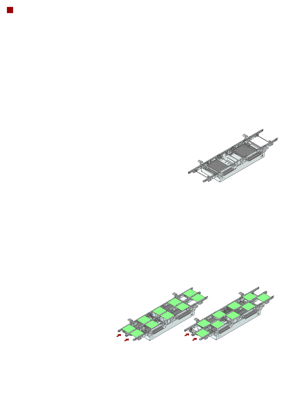
Flexible dual conveyor:
synchronous mode
Flexible dual conveyor:
asynchronous mode
Single conveyor
15
PCB Conveyor
Technical Data
Single conveyor Flexible dual conveyor Dual conveyor in
Single conveyor mode
Standard dimensions
(length x width)
50 x 50 mm² to
368 x 460 mm²
50 x 50 mm² to
368 x 216 mm²
50 x 50 mm² to
368 x 380 mm²
Wide board
configuration
50 x 50 mm² to
368 x 508 mm²
50 x 50 mm² to
368 x 242 mm²
Long board option 50 x 110 mm² to
610 x 460 mm²
50 x 120 mm² to
610 x 216 mm²
50 x 120 mm² to
610 x 380 mm²
Long board option and
Wide board configuration
50 x 110 mm² to
610 x 508 mm²
50 x 120 mm² to
610 x 242 mm²
PCB thickness Standard 0.3 mm to 4.5 mm (± 0.2 mm) (others available on request)
PCB warpage see page 16
PCB weight max. 3 kg
Clearance on PCB under-
side
25 mm ± 0.2 mm (standard)
max. 40 mm ± 0.2 mm (option)
PCB transport height 830 mm ± 15 mm (standard)
900 mm ± 15 mm (option)
930 mm ± 15 mm (option)
950 mm ± 15 mm (SMEMA option)
Type of interface SMEMA / Siemens
Component-free PCB han-
dling edge
3 mm
PCB changeover time < 2.5 s
PCB positioning accuracy ± 0.5 mm
Flexible dual conveyor Conveyor mode: synchronous or asynchronous
(selected via the software)
Flexible dual conveyor Components to be placed on each conveyor track: same or different
Flexible dual conveyor PCB width on each conveyor track: same or different
Bad fiducial recognition Single conveyor: standard
Synchronous dual conveyor: standard (no global ink spot)
Asynchronous dual conveyor: standard
Automatic electrical width
adjustment
Synchronous dual conveyor: standard
Asynchronous dual conveyor: standard
Manual width adjustment Single conveyor: standard
Fixed conveyor side Right or left