00196622-03_OM_WPC5_6_EN.pdf - 第39页
Operator Tasks Controls and Displays Operating Manual SIPLACE WPC5/WPC 6 39 5 5 O p e r a t o r T a s k s Operator Tasks 5.1 5 . 1 C o n t r o ls a n d D is p la y s Controls and Displays The main switch and the EMERGENC…
Setting up and Commissioning
Adjusting the WPC Height from 900mm to 930mm 4.2.4 Undocking the WPC5/WPC6
38 Operating Manual SIPLACE WPC5/WPC6
Operator Tasks
Controls and Displays
Operating Manual SIPLACE WPC5/WPC6 39
5
5 Operator Tasks
Operator Tasks
5.1
5.1 Controls and Displays
Controls and Displays
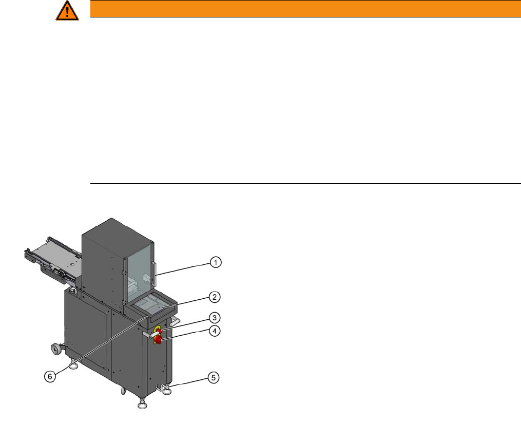
The main switch and the EMERGENCY STOP button are located on the back of the Wafflepack
Changer.
Main power switch in the OFF position
The main power switch disconnects the three phases U, V and W from the power supply.
Main power switch in the ON position
After switching on the main switch, the power supply provides the voltages needed to operate the WPC.
EMERGENCY STOP button
When you press the EMERGENCY STOP button, the power supply to the lifting and feed axes is inter-
rupted and the whole system comes to a halt.
WARNING
Hazardous Voltages
The following power supply components still carry potentially lethal voltages even if the main
power switch is switched off:
- Feed in terminals
- Line filter
- Cable connection terminals for main switch
Therefore incorrect use of the machine may lead to death or severe injury and considerable
damage to equipment.
► Always follow the applicable accident prevention and DIN regulations (particularly DIN EN
60 204, part 1) and the applicable regulations in your own country.
► The safety covers on the Wafflepack Changer may ONLY be opened by appropriately qual-
ified and trained personnel.
1. Safety door of the tray storage unit
2. Flap for loading the Non-Stop Module (only at WPC6)
3. EMERGENCY STOP button
4. Main power switch
5. Crank handle for lifting or lowering the trolley carriage
6. Non-Stop Module start button (only WPC6)
Operator Tasks
Inserting the Waffle Pack Tray Carrier
40 Operating Manual SIPLACE WPC5/WPC6
5.2
5.2 Inserting the Waffle Pack Tray Carrier
Inserting the Waffle Pack Tray Carrier
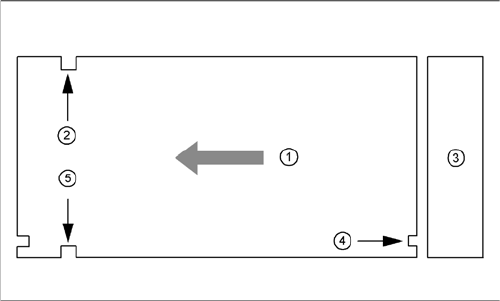
The waffle pack tray carrier is checked to ensure that it has been correctly inserted.
Make sure that the driver grooves (2) and (5) for the waffle pack tray carrier point towards the front, when
viewed in the direction of transport.
The control grooves (4) for the individual waffle pack tray carriers must be aligned above one another
and must point towards the waffle pack tray storage unit (3).
Legend
1. Transport direction
2. Driving groove free
3. Waffle pack tray storage unit
4. control groove
5. Driving groove for the feed arm