00196622-03_OM_WPC5_6_EN.pdf - 第49页
Operator Tasks 5.6.1 Basic View Functions at the Station Com puter (SR704.xx) Operating Manual SIPLACE WPC5/WPC 6 49 5.6 5 . 6 F u n c t io n s a t t h e S t a t io n C o m p u t e r ( S R 7 0 4 . x x ) Functions at the …
Operator Tasks
Functions at the Station Computer (SR703.xx) 5.5.3 Options
48 Operating Manual SIPLACE WPC5/WPC6
5.5.3
5.5.3 Options
Options
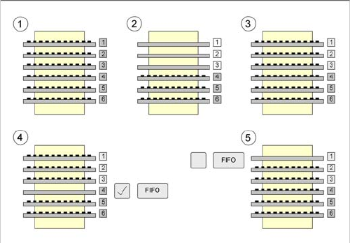
The WPC view enables you to activate the FiFo strategy as an option.
FiFo stands for "First in - First out". This means that whatever is configured first will also be made avail-
able for placement in the machine first.
The differences with the FiFo pickup strategy switched on and off are explained below:
Legend
1. The WPC has been set up with six tray carriers, containing the same components.
2. The tray carriers 1, 2 and 3 are taken out of the tower in turn and made available for component
placement.
3. The empty tray carriers 1, 2 and 3 are then refilled with the same component by the operating staff
and the WPC5 is set to full.
4. If the FiFo pickup strategy is activated, tray 4 will now be made available. The WPC5 continues from
where it stopped. The sequence continues with 4, 5, 6, 1, 2, 3.
5. If the FiFo pickup strategy is not activated, tray 1 will now be made available. The WPC5 sees the
full tower and starts from the beginning again. The sequence continues with 1, 2, 3, 4, 5, 6.
Operator Tasks
5.6.1 Basic View Functions at the Station Computer (SR704.xx)
Operating Manual SIPLACE WPC5/WPC6 49
5.6
5.6 Functions at the Station Computer (SR704.xx)
Functions at the Station Computer (SR704.xx)
5.6.1
5.6.1 Basic View
Basic View
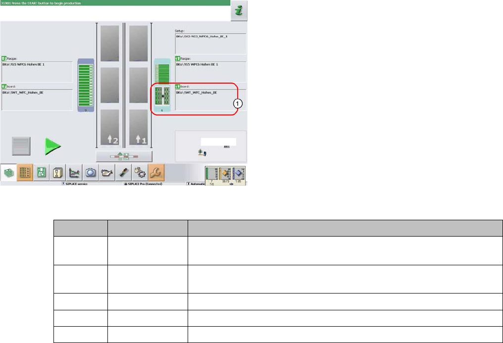
The WPC icon (1) can be displayed in various colors in the basic view. These mean:
The display applies equally to the WPC5/WPC6 and to the feeder modules, which are set up on the re-
maining feeder locations, next to the WPC5/WPC6.
The basic view shows the SIPLACE machine from above.
The PCB conveyor runs through the center. The locations
are positioned on the right and left. The location of the
WPC5/WPC6 is shown as item (1) in this example.
WPC color Component color Meaning
Gray - - - No component in WPC5/WPC6 / feeder module configured or no setup
defined.
Gray Green A setup is present and one or more components are defined for this lo-
cation.
Gray Red / green Empty waffle pack trays/ tracks in WPC5/WPC6 / feeder module
Red Red / green Track error at this location (WPC5/WPC6 / feeder module)
Yellow Red / green Production was continued although the WPC is in the refill position.
Operator Tasks
Functions at the Station Computer (SR704.xx) 5.6.2 WPC5/WPC6 Functions
50 Operating Manual SIPLACE WPC5/WPC6
5.6.2
5.6.2 WPC5/WPC6 Functions
WPC5/WPC6 Functions
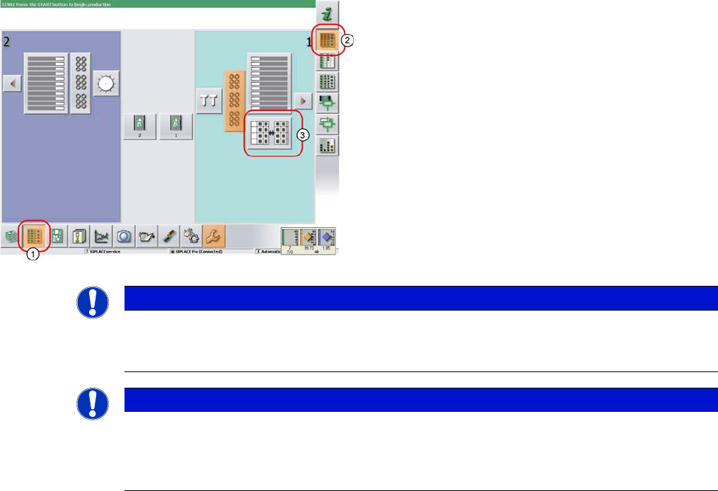
► In the tool bar of the main view click on the icon (1) for
the functions Feeder, Locations….
► Click on the icon (2). The user interface will switch to
the view Functions > Locations > WPC.
► Click on the icon (3) for the WPC5/WPC6 at the rele-
vant location (location 1 here).
The Setup > Locations > WPC view will be shown for
the selected Location.
NOTICE
WPC icon
The icon for the WPC5/WPC6 will only be shown for the location if a WPC5/WPC6 is really pre-
sent there.
NOTICE
Main view
If there is a setup available for the WPC5/WPC6, this will be shown as an icon in the diagram
of the relevant WPC in the main view.
If you click on this the WPC view will be opened for the WPC5/WPC6 at the selected location.