SPS Configuration SX1 - 2-Version-2.pdf - 第9页
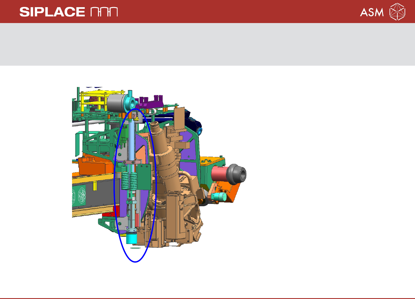
20.04.2017 Page 9 Confi gura ti on Sma rt Pin Suppor t (SPS) on SX1/ 2 The SP S uni t is m ounted on the l eft side of the head hol der . User M an ual SP S: 00197001 - xx A ssembly I n stru ction SP S SX 1/2: 00197002 -…

20.04.2017 Page 8
Summary
Parts for SIPLACE Smart Pin Support (SPS) on SX1/2
Sales-Article No.:119992 PinPicker SX1/2
Sales-Article No.:119997 Magazine Q10
Sales-Article No.:119996 Magazine L10
Sales-Article No.:119995 for 5 pieces Pins
Option: If no stationary camera is installed on location 1 or 2 and you want to mount
a Q10 magazine, an additional support plate is necessary!!!
For Location 1: 1x 03070836-xx Support plate
4x 03045087-xx Screws M6x12
4x 00311385-xx index pins
For Location 2: 1x 03070862-xx Support plate
4x 03045087-xx Screws M6x12
4x 00311385-xx index pins DIN 6325
20.04.2017 Page 9
Configuration Smart Pin Support (SPS) on SX1/2
The SPS unit is mounted on the left side of the head holder.
User Manual SPS: 00197001-xx
Assembly Instruction SPS SX1/2: 00197002-xx
20.04.2017 Page 10
Configuration SPS for SX2/SX1
To reduce the diversity of configurations of the SPS magazines, the following variants
have been be defined:
1. For the SX1 it is not possible to configure an SPS magazine on location 2, whether if
there a single- or dual conveyor.
2. For the SX2, only the SPS magazine Q10 on location 2 will be supported if a WPC
with two stationary cameras or 3D-coplan is mounted on location 1. The support
plate for location 2 is necessary.
3. The IC - Camera is not a precondition to use the Q10 magazine, but if no
IC camera installed, the Support plate 1 for location 1 is necessary.