00193351-06_RI_Vacuum_pump_de en.pdf - 第52页
2 Retrofit instructions for vacuum pump SIPLACE HS-50/HS-60/D4/S-25HM/S-27HM/HF-Series 07/2011 Edition 50 2 2 : Open the compressed air stopcock. : Pull the compressed air supply ba ck into the placement machine. : Close…
SIPLACE HS-50/HS-60/D4/S-25HM/S-27HM/HF-Series 2 Retrofit instructions for vacuum pump
07/2011 Edition
49
2
: Remove the blind plugs.
: Connect the two 12 mm hoses to the new compressed air distributor (only C&P placement
heads).
: Plug both blind plugs into the open connections of the compressed air distributor.
2
2.5.4 Change of vacuum generator
: Change the vacuum generator DLM2 against the vacuum generator for vacuum pump.
2
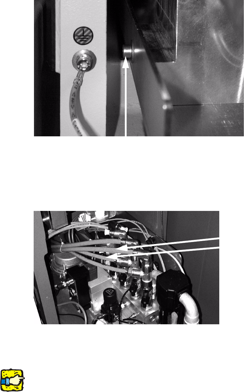
Mind the right allocation of hoses! 2
Fixing screw (thread is there, eventually drill a hole
Change hose (12 mm)
against blind plugs

2 Retrofit instructions for vacuum pump SIPLACE HS-50/HS-60/D4/S-25HM/S-27HM/HF-Series
07/2011 Edition
50
2
2
: Open the compressed air stopcock.
: Pull the compressed air supply back into the placement machine.
: Close the door of the compressed air supply.
: Switch the placement machine on at the main switch.
2
2
For checking the vacuum values see page 23 ff. 2
2
2
2
2
2
2
2
2
2
2
2
2
2
2
SIPLACE HS-50/HS-60/D4/S-25HM/S-27HM/HF-Series 2 Retrofit instructions for vacuum pump
07/2011 Edition
51
2.6 Technical Information for retrofitting a vacuum
pump on HS60 / S27HM machines
The star of the DLM heads is moved to a parked position between two star steps where the hold-
ing and pickup circuits are connected via the vacuum distributor. 2
However, this means that the activated Venturi pickup circuit evacuates the thick vacuum hose via
the holding circuit (only when the vacuum pump is switched off) and within a period of a few min-
utes, draws water from the pump. The water serves as a sealant in the water ring pumps. The
series pump with sound-proof cover is therefore fitted with a non-return valve to prevent this and
an intake air filter to prevent contamination of the pump. 2
For this reason, the pump should always run when the machine is switched on. 2
Mutual influences of several machines on one pump: 2
The parked position connects the pickup and holding circuits. This means that the there is a mu-
tual influence between the vacuum circuits of the different machines, because all the holding cir-
cuits are interconnected.
For this reason, all machines must always be running if they are operated with a vacuum pump.
This ensures that the Venturi pickup circuit maintains the vacuum. 2
If individual machines connected to the same pump are to be switched off, a stop cock must be
introduced into the vacuum infeed.
It is generally recommended that a stopcock is incorporated upstream of each machine.
If this is not done, air is drawn in backwards through the silencer via the deactivated pickup circuit
by the other machines over the vacuum hose of the pump. This leads to a reduced vacuum. 2
Only if the nozzles of all heads are in a vertical position when the machine is switched off do the
machines not influence each other if no stopcock is fitted. 2
Checking whether the holding circuit vacuum system is airtight after retrofitting: 2
Procedure: Measure the vacuum with an external pressure gauge at the measuring point of the
vacuum distribution block and then at an open nozzle in the holding circuit of the head. 2
The difference should be no more than 20-30 mbar if everything is airtight. 2
If, however, the vacuum is tested in the holding circuit with closed nozzles, a different value can
be shown if an offset has been defined in the vacuum board. For this reason, it is sensible to carry
out the measurements at the head and the vacuum distributor with the same gauge. 2
2
2