SIPLACE DX4-Spec-设备性能参数-EN-DMS - 第13页
13 SIPLACE Placement Head SIPLACE SpeedStar (C&P20) SIPLACE S peedS tar component camera type 23 (C&P2 0) S tandard- functions High-resolution camera, vacuum sensor , force measurement, component sen- sor , integ…
12
SIPLACE Placement Head
Overview
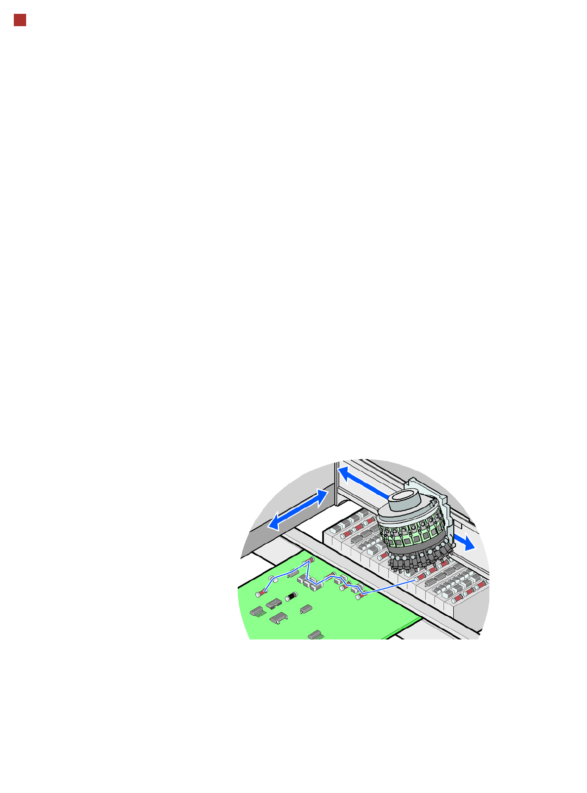
Collect&Place principle
The SIPLACE SpeedStar
operates according to the
Collect&Place principle i.e.
one cycle includes pickup or
"collection" of 20 compo-
nents, their optical centering
on the board and their rota-
tion into the required place-
ment angle and position.
They are then placed gently
and accurately onto the PCB.
This principle is particularly
suitable for high-speed
placement of standard and
01005 components.
Control and self-learning
functions
The reliability of the
SIPLACE placement heads
can be enhanced even fur-
ther with various checking
and self-learning functions.
• Component sensor
Checks the presence of
the components on the
nozzle before the pickup
and placement process
• Digital camera
Checks the position of
each component on the
nozzle. This check is per-
formed in a single step,
with no extra time involved
but with optimum scan-
ning of each individual
component.
• Force measurement
Monitors the prescribed
component set-down
force.
The sensor stop proce-
dure enables compensa-
tion of height differences
during pickup and PCB
warpage during place-
ment.
• Vacuum sensor
Checks whether the com-
ponent was correctly
picked up or placed.
13
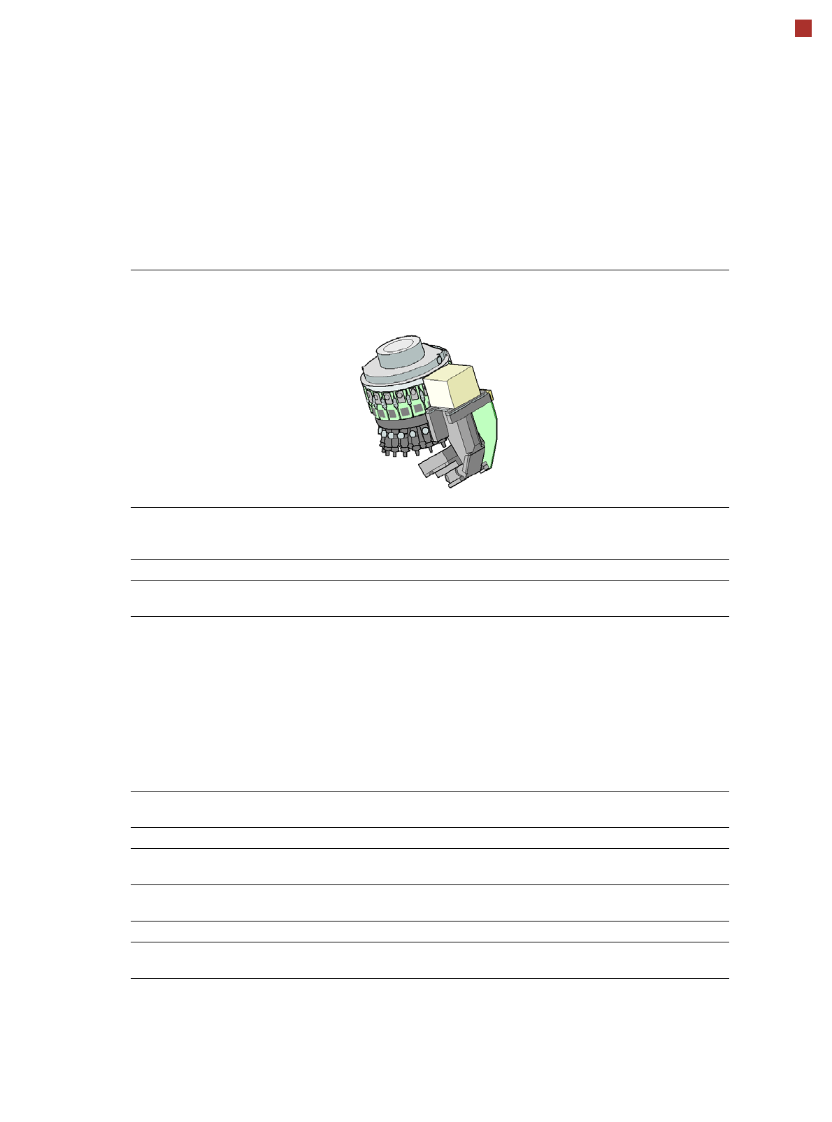
SIPLACE Placement Head
SIPLACE SpeedStar (C&P20)
SIPLACE SpeedStar
component camera type 23
(C&P20)
Standard-
functions
High-resolution camera, vacuum sensor, force measurement, component sen-
sor, integrated turning station per segment, PCB warpage check, individual
image of each component
Options Nozzle changer, special nozzles
Component range
a
a) Please note that the placeable component range is also affected by the pad geometry, the customer-specific
standards, the component packaging tolerances and the component tolerances.
01005 to 2220, Melf,
SOT, SOD
Component spec.
max. height
min. lead pitch
min. lead width
min. ball pitch
min. ball diameter
min. dimensions
max. dimensions
max. weight
4 mm
0.25 mm
0.1 mm
0.4 mm
0.2 mm
0.4 mm x 0.2 mm
6mm x 6 mm
1 g
Programmable set-down
force
1.5 N - 4.5 N
Nozzle types 10xx, 11xx, 12xx
X/Y accuracy
b
b) Accuracy values measured in accordance with vendor-neutral IPC standard.
± 41 µm/3
± 55 µm/4
Angular accuracy ± 0.5° / 3
± 0.7° / 4
Illumination levels 5
Possible illumination level
settings-
256
5
14
SIPLACE Placement Head
Nozzle Changers
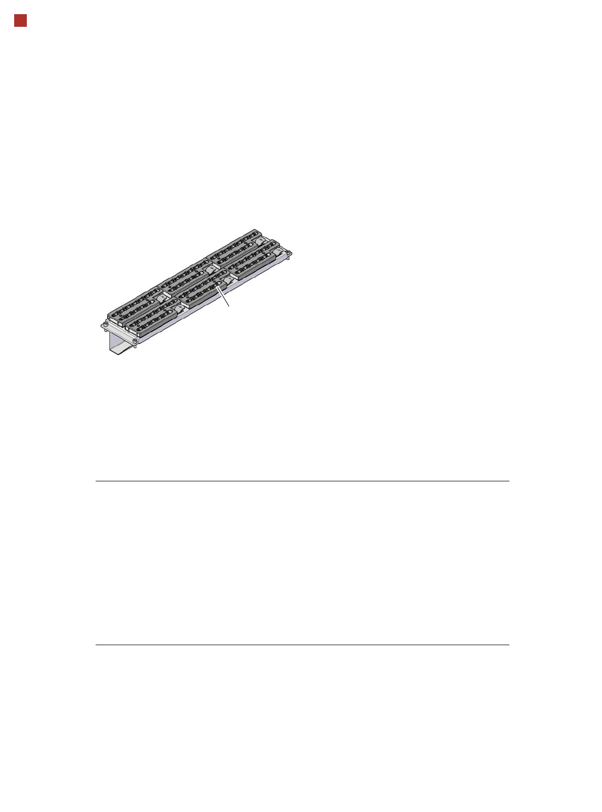
Description
Nozzle changers increase
the flexibility of the placement
heads when it comes to pro-
cessing different compo-
nents. The nozzle
configuration can be rapidly
adjusted to changing place-
ment jobs. Precisely defined
positions and perfect nozzle
seat in the garage ensure
minimum radial eccentricity
on the placement head.
The nozzle changers for the
SpeedStar are fitted with a
monitoring device which
checks whether the nozzle
magazine is seated correctly
on the mount.
Nozzle changer for the SpeedStar
Technical Data
Dimensions (length x width x height) 449 mm x 94.5 mm x 79 mm
Number of magazines
Location 1 and 3:
Location 2 and 4:
6
a
4
a
a) All magazines in the nozzle changer must be configured.
Number of nozzle garages
Location 1 and 3:
Location 2 and 4:
72
48
Standard configuration 6 magazines with 72 nozzle garages
Nozzle types 10xx, 11xx and 12xx
Compressed air connection 0.45 MPa (4.5 bar)
Magazine for 12
type 10xx, 11xx and 12xx nozzles