SIPLACE DX4-Spec-设备性能参数-EN-DMS - 第19页
19 PCB Warpage PCB warpage across the directio n of travel max. 1 % of the PCB diagonal, but no t exceeding 2 mm PCB warpage on the co nveyor PCB warpage during placement PCB transport direction PCB warpage d ownwards ma…
18
PCB Conveyor
I-Placement
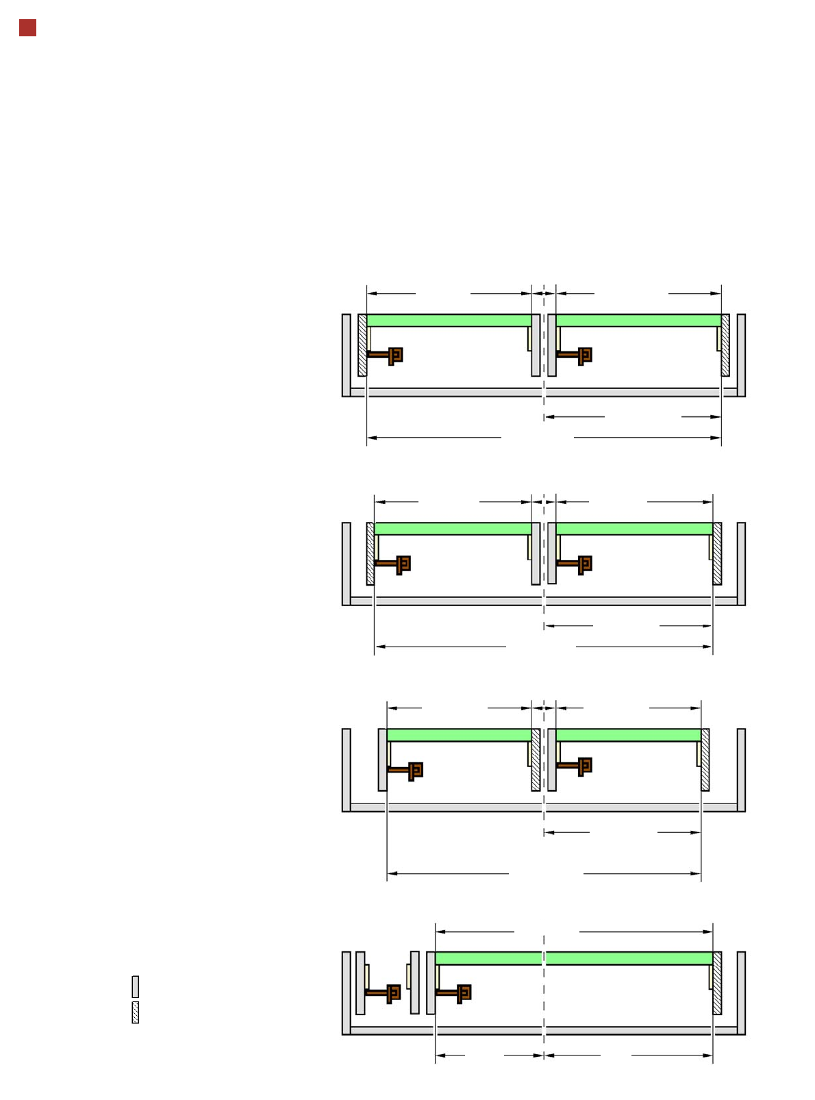
Alternating Placement Mode
Alternating or
I-Placement mode
Distance of outer conveyor
edges: 680 mm, 2 lanes, outer
conveyor edges fixed
Alternating or I-Placement
mode
Distance of outer conveyor
edges: 560 mm, 2 lanes, outer
conveyor edges fixed
Alternating placement mode
Distance of outer conveyor
edges: 535 mm, 2 lanes, right
conveyor edges fixed
a
Alternating placement mode
Distance of outer conveyor
edges: 601 mm, dual conveyor
in single conveyor mode, right
conveyor edge fixed
a
max. 325
Movable conveyor side
Stationary conveyor side
Only the settings with fixed conveyor edge on the right are shown. A setting with the stationary conveyor edge on the left is also
possible. All dimensions in millimeters.
max. 325
344 ± 17.5
680 (27“)
min. 35
max. 262
281 ± 17.5
560 (22“)
min. 35
max. 262
- 344
+ 258
max. 250
268 ± 18
min. 35
max. 250
535 (21“)
max. 601
19
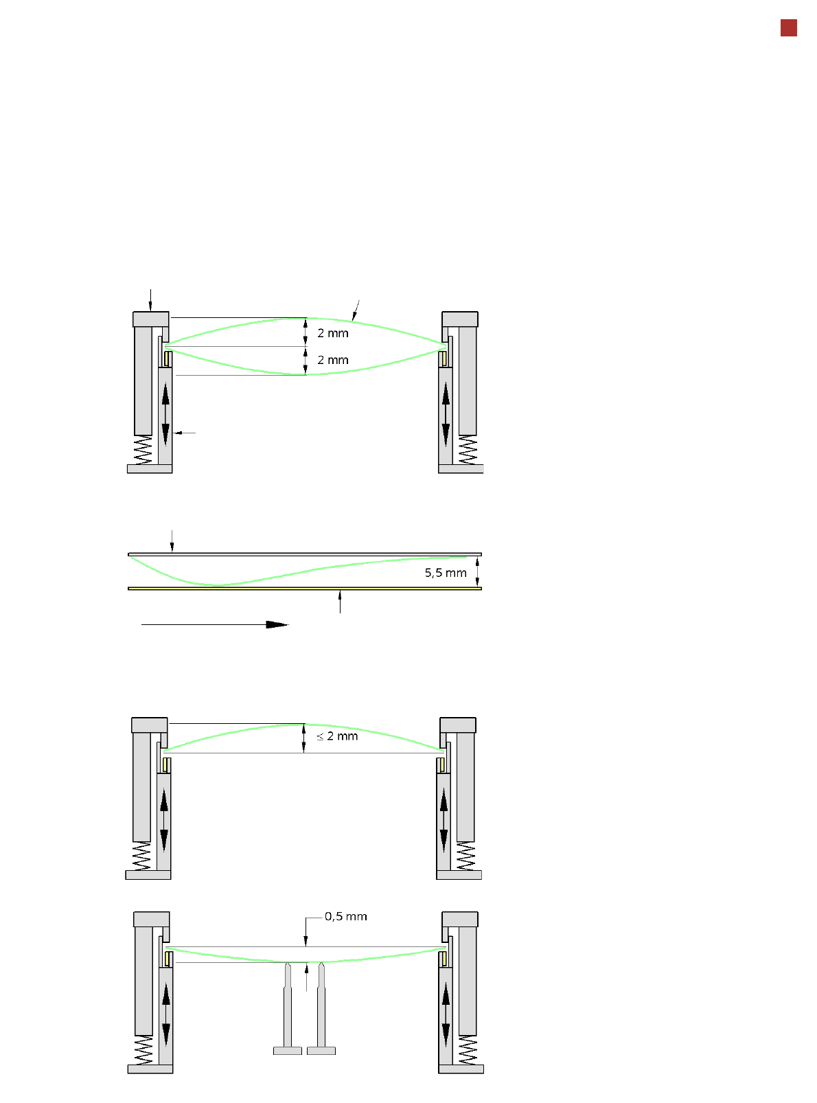
PCB Warpage
PCB warpage across the direction of travel
max. 1 % of the PCB diagonal, but not
exceeding 2 mm
PCB warpage on the conveyor
PCB warpage during placement
PCB transport direction
PCB warpage downwards max. 0.5 mm
Use the magnetic pin supports, to achieve
this value.
Conveyor belt
Fixed clamped edge
PCB warpage in direction of travel
+ PCB thickness < 5.5 mm
Fixed clamped edge
Movable clamping device
When there is warpage under 2 mm, the
inkspots in the center of the board are also
within the focus of the digital camera. When
all the tolerances are taken into account,
this value is reduced to 1.5 mm.
You should also note that the warpage
reduces the component height.
Magnetic pin support
PCB
20
Component Feeding
SIPLACE DX4 Table
In its default configuration,
the SIPLACE DX4 has four
DX tables which, if used with
SIPLACE 2x8mm X tape
feeder modules, can be set
up to achieve capacity of up
to 40 tracks each for accom-
modating component types.
Feeder modules can be torn
down or added to the config-
uration even during ongoing
placement.
External setup tables, which
can be equipped with a sin-
gle-track feeder module-
energy interface, help to sup-
ply the feeder modules with
materials. These are then
easily and quickly docked
into the machine.
The component feeders are
at rest during the placement
process - allowing tapes to
be spliced without stopping
the machine.
With the help of an optional
component barcode reader
and the Setup Center option,
the barcodes on the tape
reels can be read and
checked.
This ensures the correct
assignment of components
to tracks and the traceability
of PCB placement with the
Traceability software.
For safety reasons, unoccu-
pied locations are fitted with
so-called dummy feeder
modules.
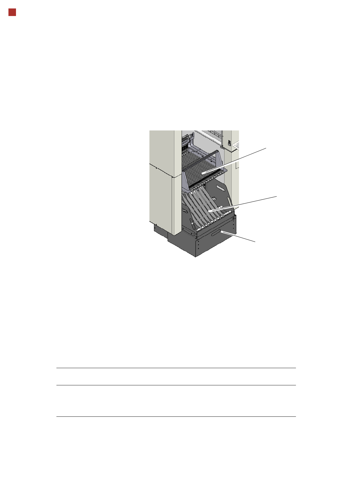
Tape container
Waste container for remaining empty
tape
DX4 table
Technical Data
Tape reel diameter 178 mm to 381 mm (7“ - 15“)
Max. component feeding
(Four DX tables for SIPLACE DX4)
Location 1 and 3:
Location 2 and 4:
74 tape feeder modules, each with 2x8 mm X
40 feeder modules, each with 2x8 mm X
34 feeder modules, each with 2x8 mm X