SIPLACE DX4-Spec-设备性能参数-EN-DMS - 第20页
20 Component Feeding SIPLACE DX4 Table In its default configuration, the SIPLACE DX4 has four DX tables which, if used with SIPLACE 2x8mm X tape feeder mo dules, can b e set up to achieve capacity of up to 40 tracks each…
19
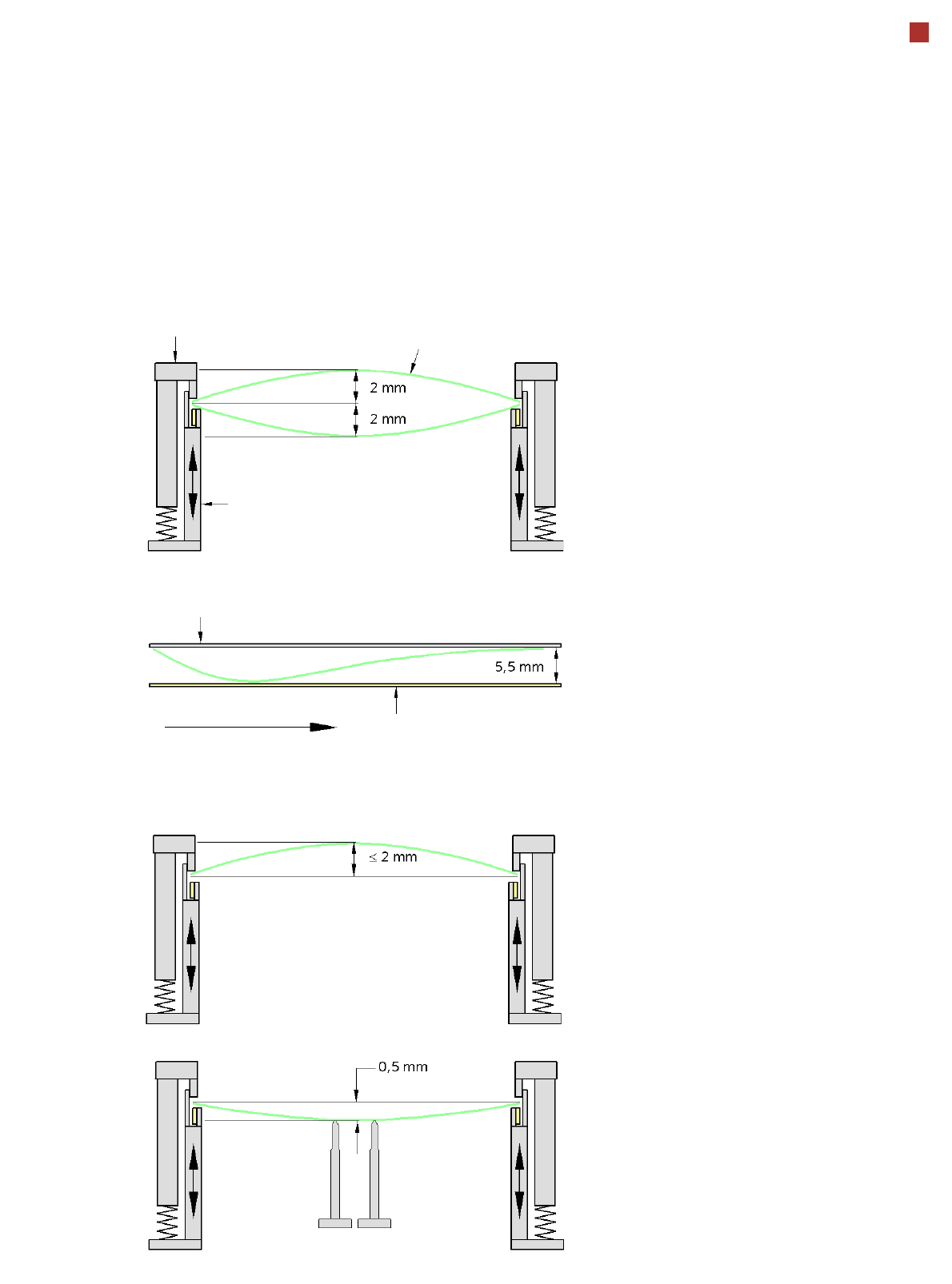
PCB Warpage
PCB warpage across the direction of travel
max. 1 % of the PCB diagonal, but not
exceeding 2 mm
PCB warpage on the conveyor
PCB warpage during placement
PCB transport direction
PCB warpage downwards max. 0.5 mm
Use the magnetic pin supports, to achieve
this value.
Conveyor belt
Fixed clamped edge
PCB warpage in direction of travel
+ PCB thickness < 5.5 mm
Fixed clamped edge
Movable clamping device
When there is warpage under 2 mm, the
inkspots in the center of the board are also
within the focus of the digital camera. When
all the tolerances are taken into account,
this value is reduced to 1.5 mm.
You should also note that the warpage
reduces the component height.
Magnetic pin support
PCB
20
Component Feeding
SIPLACE DX4 Table
In its default configuration,
the SIPLACE DX4 has four
DX tables which, if used with
SIPLACE 2x8mm X tape
feeder modules, can be set
up to achieve capacity of up
to 40 tracks each for accom-
modating component types.
Feeder modules can be torn
down or added to the config-
uration even during ongoing
placement.
External setup tables, which
can be equipped with a sin-
gle-track feeder module-
energy interface, help to sup-
ply the feeder modules with
materials. These are then
easily and quickly docked
into the machine.
The component feeders are
at rest during the placement
process - allowing tapes to
be spliced without stopping
the machine.
With the help of an optional
component barcode reader
and the Setup Center option,
the barcodes on the tape
reels can be read and
checked.
This ensures the correct
assignment of components
to tracks and the traceability
of PCB placement with the
Traceability software.
For safety reasons, unoccu-
pied locations are fitted with
so-called dummy feeder
modules.
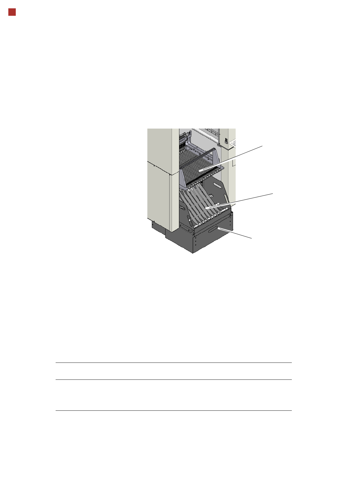
Tape container
Waste container for remaining empty
tape
DX4 table
Technical Data
Tape reel diameter 178 mm to 381 mm (7“ - 15“)
Max. component feeding
(Four DX tables for SIPLACE DX4)
Location 1 and 3:
Location 2 and 4:
74 tape feeder modules, each with 2x8 mm X
40 feeder modules, each with 2x8 mm X
34 feeder modules, each with 2x8 mm X
21
Component Feeding
SIPLACE DX Changeover Table (Option)
DX changeover table
The DX changeover tables
are independent and easily
maneuverable modules. The
SIPLACE DX4 machines can
accommodate four DX
changeover tables, each with
40 tracks. Just like the fixed
DX tables, the DX change-
over tables are optimized for
the use of 2x8 mm SIPLACE
tape feeder modules when
using 8 mm tapes. By using
20 of these feeder modules,
you can achieve a full setup
capacity of 40 8mm tracks.
The tape reels are taken up
into the tape container of the
DX changeover table. A cut-
ting device on the machine
automatically cuts the used
tape material. The DX
changeover tables can be
set up directly on the
machine or at an external
setup area with feeder mod-
ules. The benefits of offline
setup are that the configura-
tions can be prepared with-
out stopping the line.
This allows the setup to be
changed very quickly using
the DX changeover table
principle. The SIPLACE DX
changeover table also sup-
port fast setting up and tear-
ing down of feeder modules
even during the placement
process.
The component feeders are
at rest during the placement
process - allowing tapes to
be spliced without stopping
the machine.
With the help of an optional
component barcode reader
and the Setup Center option,
the barcodes on the tape
reels can be read and
checked.
This ensures the correct
assignment of components
to tracks and the traceability
of PCB placement with the
Traceability software.
For safety reasons, unoccu-
pied locations are fitted with
so-called dummy feeder
modules.
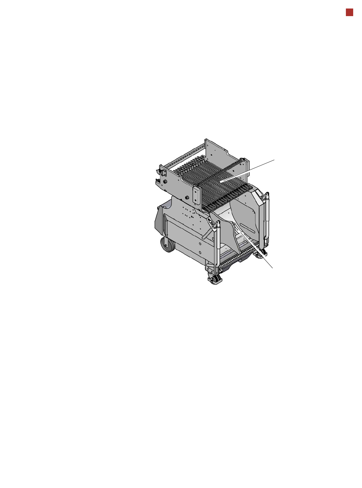
DX changeover table
Tape container
Changeover table