SIPLACE DX4-Spec-设备性能参数-EN-DMS - 第24页
24 Digital SIPLACE Vision System The digital Vision system ensures fast and reliable component recognitio n, cou- pled with user-friendly ha n- dling. The s ystem identif ies each individu al compone nt by its geometry a…

23
Component Feeding
X Tape Feeder Modules
SIPLACE X tape feeder
modules are intelligent tape
feeder modules for flexible
production environments,
which simplify upgrading and
conversion tasks consider-
ably. All SIPLACE X feeder
modules support tape splic-
ing as a standard, which pre-
vents machine stoppages
when refilling.
The benefits at a glance:
Conversion-friendly
• The SIPLACE X tape
feeder modules and the
intelligent SIPLACE soft-
ware solutions provide a
fast and efficient change-
over process.
• Omega profiles on the
tape feeder module and
table facilitate safe and
reliable upgrading and
conversion of tape feeder
modules during ongoing
production.
Robust
• Innovative drive technolo-
gy extends the service life
of the X tape feeder mod-
ules.
Intelligent
• A unique tape feeder mod-
ule ID ensures a precise
assignment of the compo-
nent to the tape feeder
module. This makes reli-
able setup verification
very simple.
• Component pitch, feeder
speed and other functions
are automatically set
when the setup program is
downloaded.
High feeding accuracy
• High-precision sensor
technology for path mea-
surement ensures highly
accurate component feed-
ing, even for 01005 place-
ments.
Operator-friendly
• Contactless data and
power transmission make
it easier to attach/remove
the tape feeder modules.
• Controls and displays sup-
port the user with current
information.
Technical Data
Tape feeder
module
L x H
[mm]
Width
[mm]
Tracks Transport
increment
[mm]
Max. tape
height
[mm]
2x8 mm X 587x200 22.9 2 1/2/4/8 3.5
8 mm X
a,b
587x200 10.8 1 1/2/4/8 3.5
12 mm X
a
587x200 22.6 2 4 - 16
c
6.5
Smart Feeder 12 mm X 587x200 22.6 2 4 - 16
b
16
16 mm X
a, d
587x200 34.4 3 4 - 20
c
25
Smart Feeder 16 mm X 587x200 22.6 2 4 - 20
b
16
Changeover time 8 s
a) PSA kit available as an option
b) The maximum number of tracks is reduced
c) In 4mm increments
d) PSA kit standard

24
Digital SIPLACE Vision System
The digital Vision system
ensures fast and reliable
component recognition, cou-
pled with user-friendly han-
dling. The system identifies
each individual component
by its geometry and color.
Even complex component
shapes, such as flip chip or
CCGA are detected with high
reliability.
This component recognition
check is performed in a sin-
gle step, with no extra time
involved but with optimum
scanning of each individual
component.
This digital Vision system is
not only used in the compo-
nent cameras but also in the
PCB camera. In addition to
the precise recognition of
components, this also guar-
antees reliable detection of
inkspots and PCB fiducials.
The benefits at a glance:
• Extremely fast and reliable
component recognition
• Shortest cycle times
• Robust measurement
based on the geometry
and color
• Straightforward program-
ming
• Offline programming of
component shapes
• Rapid introduction of new
products (NPI)
• Open architecture allows
you to quickly adapt to
new requirements
• Optimum placement
results based on individ-
ual measurement of each
component
The SIPLACE Vision sys-
tem offers inspection rou-
tines and functions to
enhance the quality of com-
ponent recognition.
The benefits at a glance:
• Maximum placement
quality
• High first pass yield
• Reduction of operating
costs
Digital vision cameras
SIPLACE SpeedStar camera, type 23
SIPLACE PCB camera, type 34
Examples of digital vision system analysis times
Evaluation times only play a role in the P&P process.
01005 9 ms
PLC44 17 ms
BGA 225 balls 18 ms
25
Digital SIPLACE Vision System
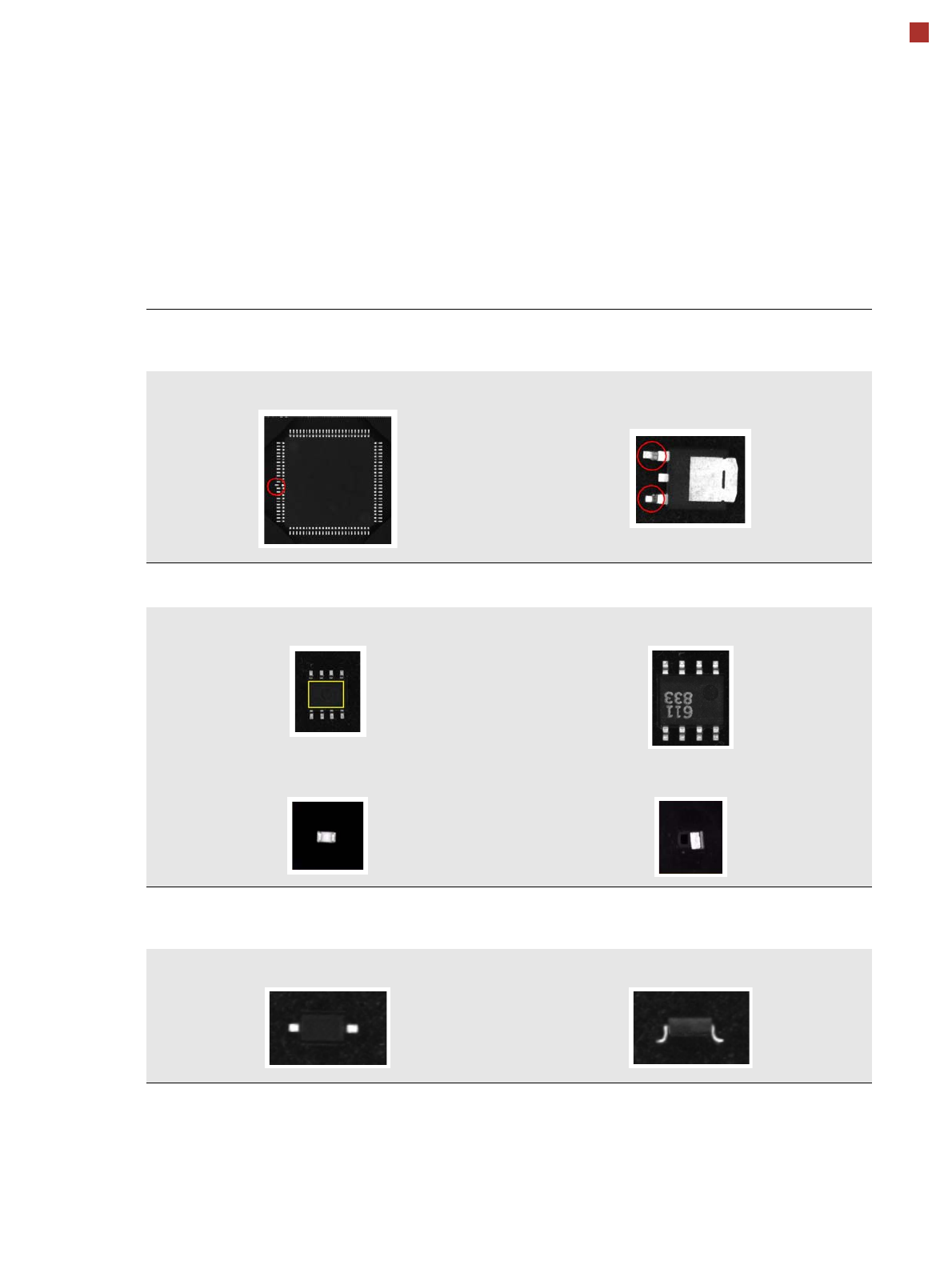
Checking the Component Quality
Overview of Key Functions
Recognizing the collinearity of components
Damaged or bent leads are recognized. This helps avoid solder-free connections during the subsequent solder-
ing process.
Damaged leads Damaged leads
Recognizing flipped (face down) or upright components
Both chip and IC component shapes (e.g. SOT) recognized in flipped (turned face down) or upright state.
SOT OK SOT “face down”
Flipped chip Chip upright
Checking the lead width
The optical checking of the lead width recognizes tilted or damaged leads. This helps to recognize e.g. diodes
with tilted leads.
Lead width OK Tilted lead