SIPLACE DX4-Spec-设备性能参数-EN-DMS - 第25页
25 Digital SIPLACE Vision System Checking the Component Quality Overview of Key Functions Recognizing the co llinearity of components Damaged or bent leads are recognized. Thi s helps avoi d solder-free connections du ri…

24
Digital SIPLACE Vision System
The digital Vision system
ensures fast and reliable
component recognition, cou-
pled with user-friendly han-
dling. The system identifies
each individual component
by its geometry and color.
Even complex component
shapes, such as flip chip or
CCGA are detected with high
reliability.
This component recognition
check is performed in a sin-
gle step, with no extra time
involved but with optimum
scanning of each individual
component.
This digital Vision system is
not only used in the compo-
nent cameras but also in the
PCB camera. In addition to
the precise recognition of
components, this also guar-
antees reliable detection of
inkspots and PCB fiducials.
The benefits at a glance:
• Extremely fast and reliable
component recognition
• Shortest cycle times
• Robust measurement
based on the geometry
and color
• Straightforward program-
ming
• Offline programming of
component shapes
• Rapid introduction of new
products (NPI)
• Open architecture allows
you to quickly adapt to
new requirements
• Optimum placement
results based on individ-
ual measurement of each
component
The SIPLACE Vision sys-
tem offers inspection rou-
tines and functions to
enhance the quality of com-
ponent recognition.
The benefits at a glance:
• Maximum placement
quality
• High first pass yield
• Reduction of operating
costs
Digital vision cameras
SIPLACE SpeedStar camera, type 23
SIPLACE PCB camera, type 34
Examples of digital vision system analysis times
Evaluation times only play a role in the P&P process.
01005 9 ms
PLC44 17 ms
BGA 225 balls 18 ms
25
Digital SIPLACE Vision System
Checking the Component Quality
Overview of Key Functions
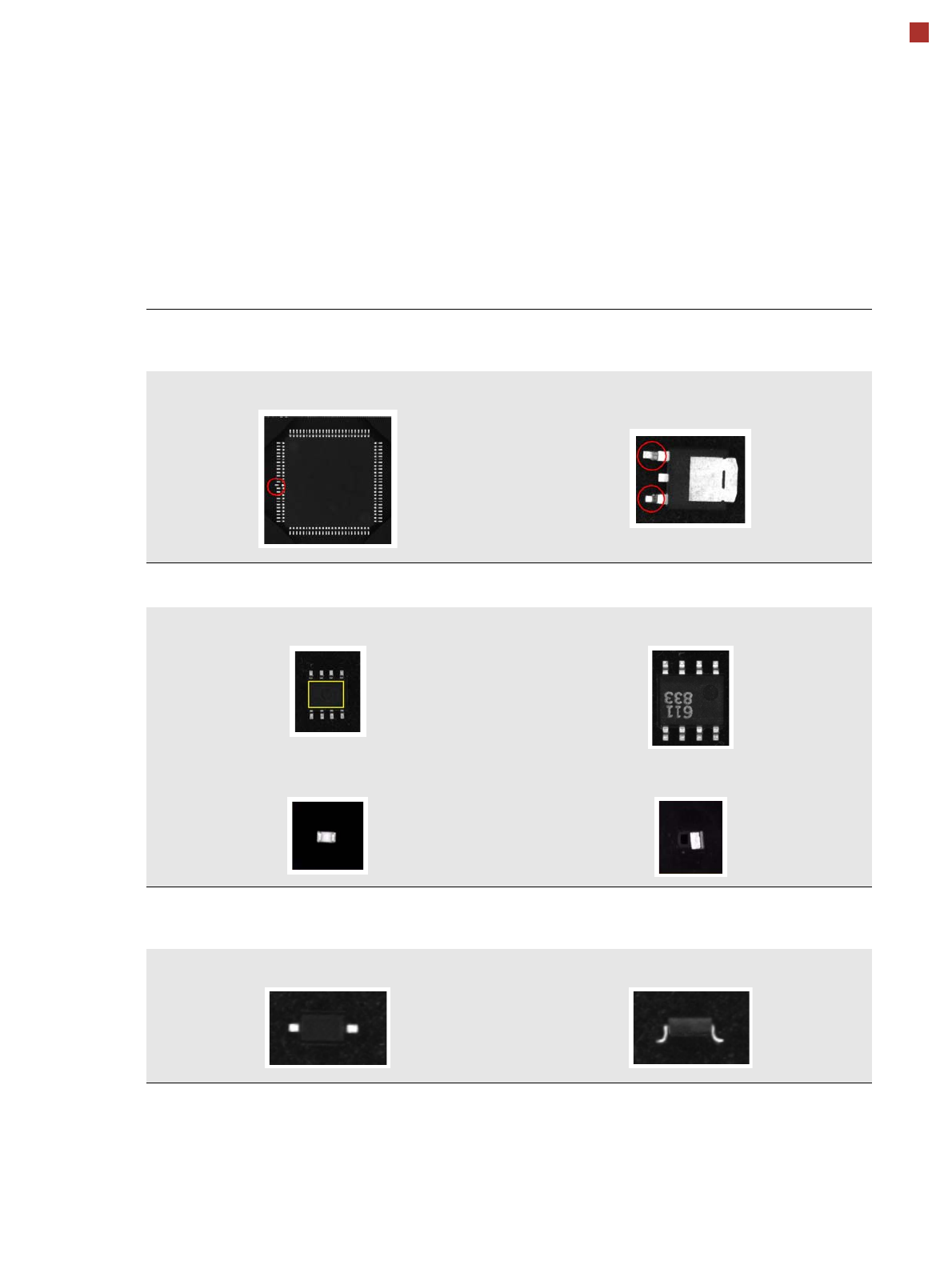
Recognizing the collinearity of components
Damaged or bent leads are recognized. This helps avoid solder-free connections during the subsequent solder-
ing process.
Damaged leads Damaged leads
Recognizing flipped (face down) or upright components
Both chip and IC component shapes (e.g. SOT) recognized in flipped (turned face down) or upright state.
SOT OK SOT “face down”
Flipped chip Chip upright
Checking the lead width
The optical checking of the lead width recognizes tilted or damaged leads. This helps to recognize e.g. diodes
with tilted leads.
Lead width OK Tilted lead
26
Digital SIPLACE Vision System
Checking the Component Quality
Overview of Key Functions
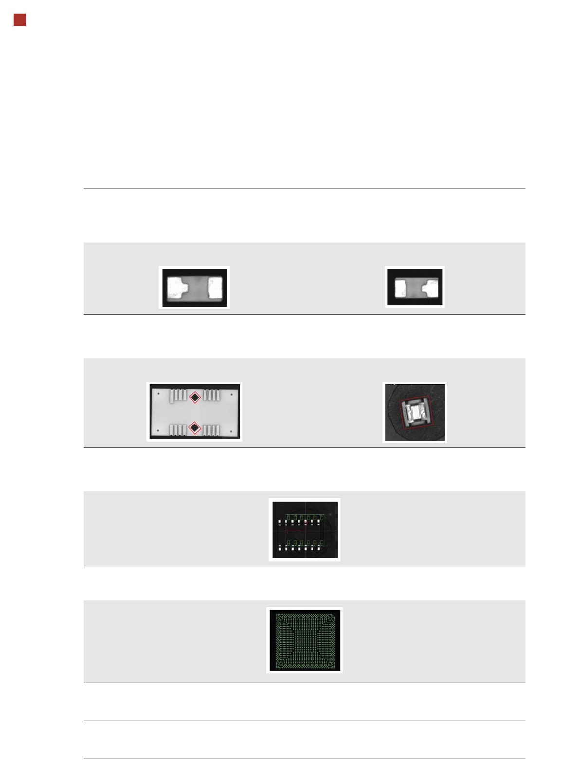
Checking the lead length
The lead length check determines whether the leads have been distorted. This inspection is possible by checking
whether leads of the same type e.g. chip shapes have different lengths. Flipped and rotated components can also
be detected.
Component OK in this position Rotated
Detecting special shapes with rectangular functions
When using certain special component shapes, it is sometimes necessary to program parts on the components or
outlines as rectangular shapes. This ensures that they can be processed more reliably.
Rectangular function on the component Rectangular component with irregular edges
Detecting incorrect component descriptions
The Vision system checks whether the position of the component corresponds to the measured Vision data. The
following example has more leads than were programmed in the component shape description.
Teaching complex BGA structures
Complex BGA structures can be taught within only a few seconds.
Placing when inkspot is not present
A fiducial can now be defined for the omission of panels. If a fiducial is found (cross, circle, etc.), this panel will be
omitted.
Checking the inner area of circular fiducials
To differentiate circular fiducials from other structures on the board, a brightness check is performed in the inner
area of these fiducials.