SIPLACE DX4-Spec-设备性能参数-EN-DMS - 第40页
40 Technical Data SMEMA Interface Signal Path 1. After swit ching on the stat ion Direction of transport Conveyor n Conveyor n +1 PCB sensor PCB sensor Station n transports PCB to transfer position Conveyor n running Con…

39
Technical Data
SMEMA Interface
Connector Assignment
Signal interface (14 pin connection socket, interface standard 1.2)
Predecessor station X1 Successor station X2
Pin 1 NOT READY + Pin 1 NOT READY +
Pin 2 NOT READY – Pin 2 NOT READY –
Pin 3 BOARD AVAILABLE + Pin 3 BOARD AVAILABLE +
Pin 4 BOARD AVAILABLE – Pin 4 BOARD AVAILABLE –
Pin 5 Not in use Pin 5 Not in use
Pin 6 Not in use Pin 6 Not in use
Pin 7 Not in use Pin 7 Not in use
Pin 8 Reserved Pin 8 Reserved
Pin 9 Reserved Pin 9 Reserved
Pin 10 Reserved Pin 10 Reserved
Pin 11 Reserved Pin 11 Reserved
Pin 12 Reserved Pin 12 Reserved
Pin 13 Reserved Pin 13 Reserved
Pin 14 Reserved Pin 14 Reserved
40
Technical Data
SMEMA Interface
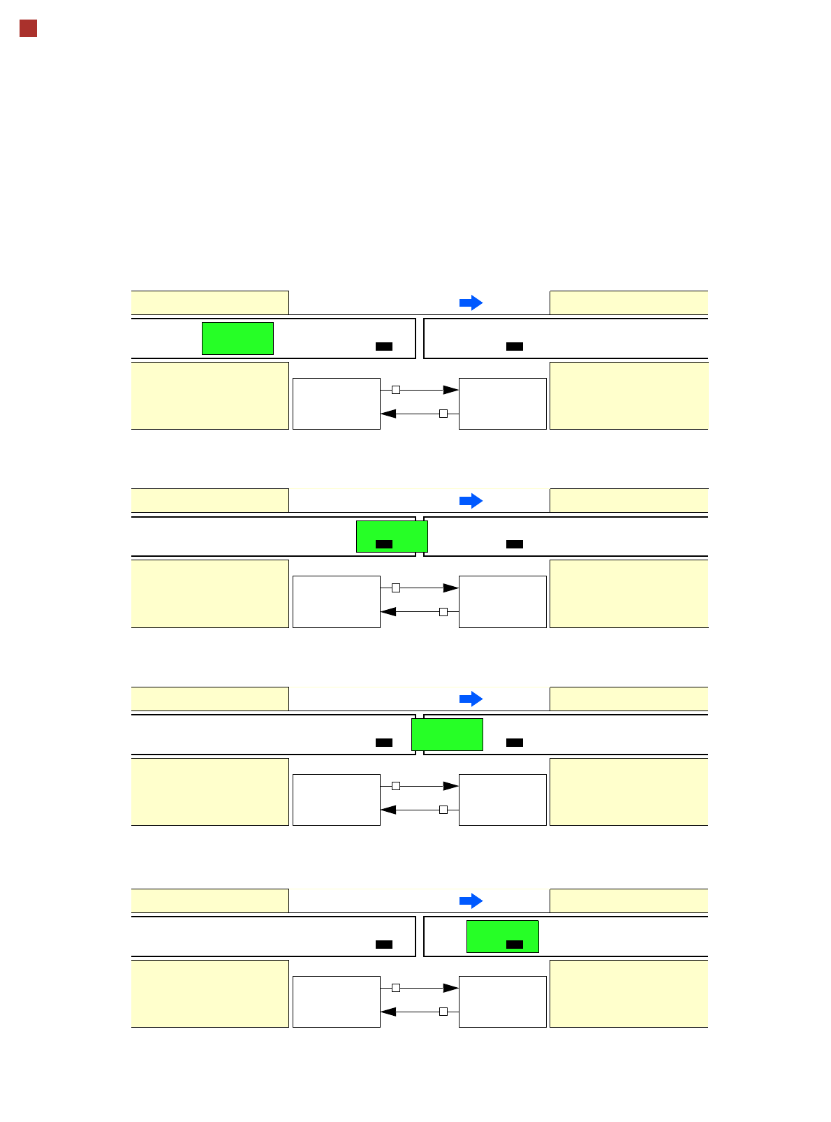
Signal Path
1. After switching on the station
Direction of transport
Conveyor n Conveyor n+1
PCB sensor PCB sensor
Station n transports PCB
to transfer position
Conveyor n running Conveyor n+1
BOARD AVAIL-
ABLE
Permission
Station n+1
is not ready
1
0
2. PCB transfer has started
Direction of transport
Conveyor n Conveyor n+1
PCB sensor
Station n transfers
PCB to station n+1
Conveyor n running Conveyor n+1 running
Station n+1 expects
PCB from station n
3. PCB is transferred
Direction of transport
Conveyor n Conveyor n+1
PCB sensor PCB sensor
Station n has just trans-
ferred PCB
Conveyor n stopped Conveyor n+1 running
Station n+1 expects PCB
from station n, PCB has
not yet arrived
PCB sensor
4. PCB transfer has been completed
Direction of transport
Conveyor n Conveyor n+1
PCB sensor PCB sensor
Station n
Conveyor n stopped Conveyor n+1 running
Station n+1
PCB has arrived
Request
NOT READY
BOARD AVAIL-
ABLE
Permission
1
1
Request
NOT READY
BOARD AVAIL-
ABLE
Permission
0
1
Request
NOT READY
BOARD AVAIL-
ABLE
Permission
0
0
Request
NOT READY
To start a new PCB transfer, both signals must be at least 50 ms "0".

41
Technical Data
Siemens Signal Interface
Connector Assignment
Signal interface (20 pin flat connector)
Predecessor station X1 Successor station X2
Pin 1 Reserved Pin 1 Reserved
Pin 2 GND 24 V- Pin 2 Reserved
Pin 3 + 24 V- Pin 3 Reserved
Pin 4 Reserved Pin 4 Reserved
Pin 5 Reserved Pin 5 GND 24 V-
Pin 6 Reserved Pin 6 + 24 V-
Pin 7 Reserved Pin 7 Reserved
Pin 8 Reserved Pin 8 Reserved
Pin 9 Reserved Pin 9 Reserved
Pin 10 Reserved Pin 10 Reserved
Pin 11 Interference signal circuit Pin 11 Interference signal circuit
Pin 12 Interference signal circuit Pin 12 Interference signal circuit
Pin 13 GND 24 V- Pin 13 GND 24 V- for permission / arrived
(galvanic isolation)
Pin 14 Arrived Pin 14 Arrived
Pin 15 Permission Pin 15 Permission
Pin 16 Reserved Pin 16 Reserved
Pin 17 Reserved Pin 17 Reserved
Pin 18 Transferred Pin 18 Transferred
Pin 19 Request Pin 19 Request
Pin 20 GND 24 V- for request / trans-
ferred (galvanic isolation)
Pin 20 GND 24 V-