SIPLACE DX4-Spec-设备性能参数-EN-DMS - 第42页
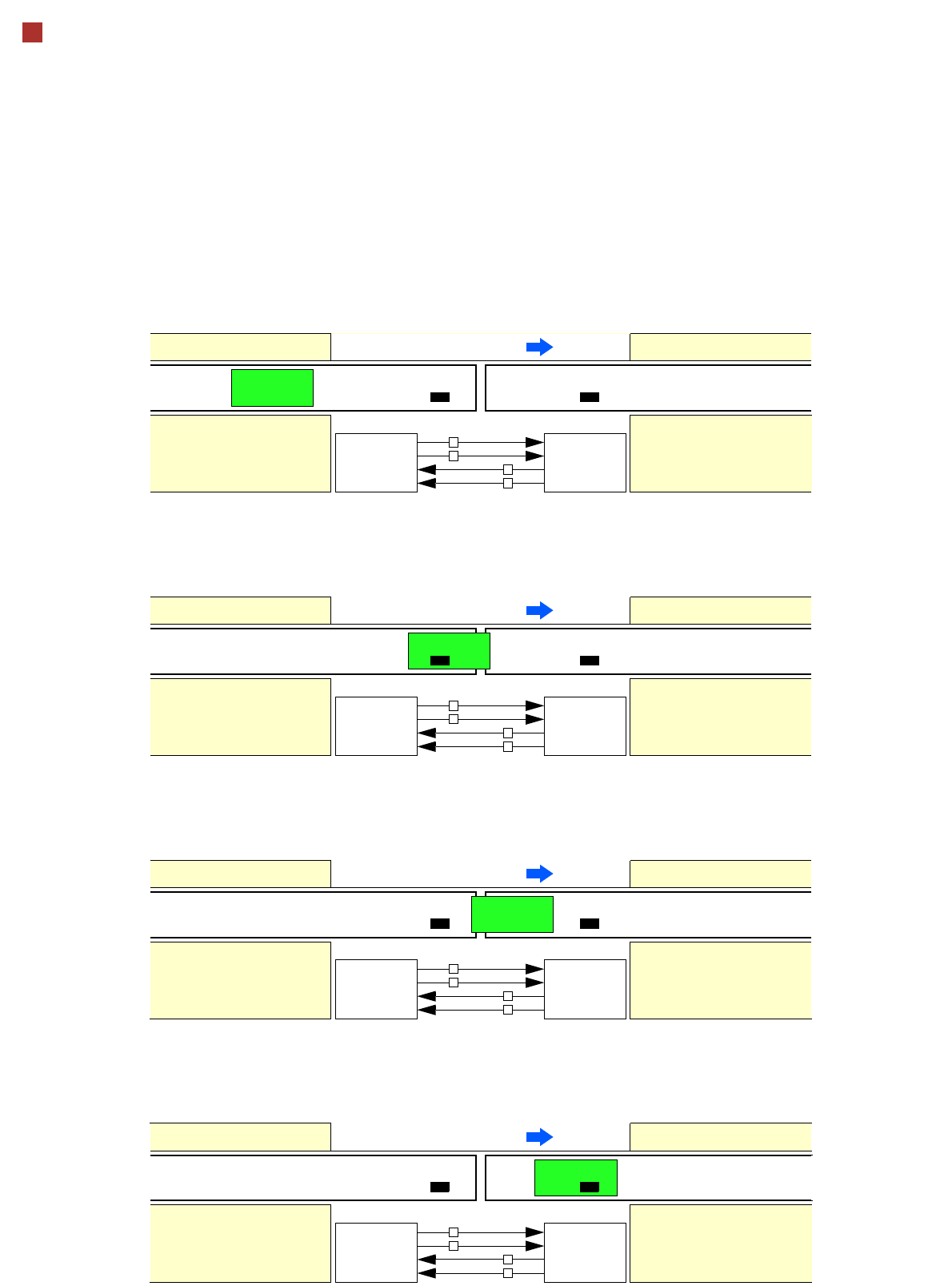
42 Technical Data Siemens Signal Interface Signal Path 1. After swit ching on the stat ion Direction of transport Conveyor n Conveyor n +1 PCB sensor PCB sensor Station n transports PCB to transfer position Conveyor n ru…

41
Technical Data
Siemens Signal Interface
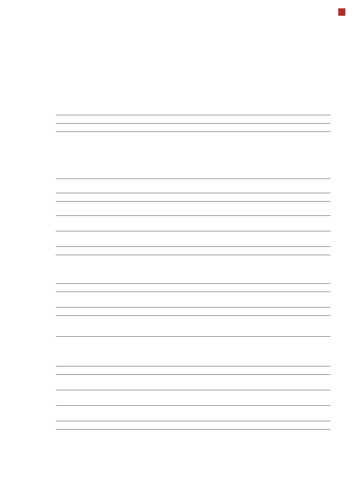
Connector Assignment
Signal interface (20 pin flat connector)
Predecessor station X1 Successor station X2
Pin 1 Reserved Pin 1 Reserved
Pin 2 GND 24 V- Pin 2 Reserved
Pin 3 + 24 V- Pin 3 Reserved
Pin 4 Reserved Pin 4 Reserved
Pin 5 Reserved Pin 5 GND 24 V-
Pin 6 Reserved Pin 6 + 24 V-
Pin 7 Reserved Pin 7 Reserved
Pin 8 Reserved Pin 8 Reserved
Pin 9 Reserved Pin 9 Reserved
Pin 10 Reserved Pin 10 Reserved
Pin 11 Interference signal circuit Pin 11 Interference signal circuit
Pin 12 Interference signal circuit Pin 12 Interference signal circuit
Pin 13 GND 24 V- Pin 13 GND 24 V- for permission / arrived
(galvanic isolation)
Pin 14 Arrived Pin 14 Arrived
Pin 15 Permission Pin 15 Permission
Pin 16 Reserved Pin 16 Reserved
Pin 17 Reserved Pin 17 Reserved
Pin 18 Transferred Pin 18 Transferred
Pin 19 Request Pin 19 Request
Pin 20 GND 24 V- for request / trans-
ferred (galvanic isolation)
Pin 20 GND 24 V-
42
Technical Data
Siemens Signal Interface
Signal Path
1. After switching on the station
Direction of transport
Conveyor n
Conveyor n+1
PCB sensor PCB sensor
Station n transports PCB
to transfer position
Conveyor n running Conveyor n+1
Request
Transferred
Permission
Arrived
Request
Transferred
Permission
Arrived
Station n+1
is ready to receive
0
0
1
0
2. PCB transfer has started
Direction of transport
Conveyor n Conveyor n+1
PCB sensor
Station n transfers
PCB to station n+1
Conveyor n running Conveyor n+1 running
Request
Transferred
Permission
Arrived
Request
Transferred
Permission
Arrived
Station n+1 expects
PCB from station n
1
0
1
0
3. PCB is transferred
Direction of transport
Conveyor n Conveyor n+1
PCB sensor PCB sensor
Station n has just trans-
ferred PCB
Conveyor n stopped Conveyor n+1 running
Request
Transferred
Permission
Arrived
Request
Transferred
Permission
Arrived
Station n+1 expects PCB
from station n, PCB has
not yet arrived
0
1
1
0
PCB sensor
4. PCB transfer has been completed
Direction of transport
Conveyor n Conveyor n+1
PCB sensor PCB sensor
Station n
Conveyor n stopped Conveyor n+1 running
Request
Transferred
Permission
Arrived
Request
Transferred
Permission
Arrived
Station n+1
PCB has arrived
0
0
0
1
43
Technical Data
Electrical Ratings, Energy Consumption and
Compressed Air Supply
Electrical ratings
Supply voltage Fuses
Main power supply
3 x 200 V~ ± 10 %; 50 Hz (North Japan)
3 x 220 V~ ± 10 %; 60 Hz (South Japan)
3 x 208 V~ ± 10 %; 50/60 Hz (U.S.A)
3 x 230 V~ ± 10 %; 50/60 Hz
3 x 380 V~ ± 10 %; 50/60 Hz
3 x 400 V~ ± 10 %; 50/60 Hz (Europe)
3 x 415 V~ ± 10 %; 50/60 Hz
3 x 25 A up to max. 3 x 32 A
3 x 25 A up to max. 3 x 32 A
3 x 25 A up to max. 3 x 32 A
3 x 25 A up to max. 3 x 32 A
3 x 16 A
3 x 16 A
3 x 16 A
Power connector
Cable 5 x 4 mm² 5 x 32 A (3 x 200 V~ / 208 V~ / 220 V~/ 230 V ~)
Cable 5 x 4 mm² with CEKON connector 5 x 16 A (3 x 380 V~ / 400 V~ / 415 V~/ V ~)
Energy consumption
Energy consumption
with vacuum pump
a
a) Vacuum pump is standard for DX4.
Nominal apparent
power
6.00 kVA
Nominal active
power
3.45 kW
Compressed air supply
Compressed air
pressure values
p
min
p
max
0.5 MPa = 5.0 bar
1.0 MPa = 10 bar
Operating pressure
0.48 MPa ± 0.025 MPa (4.8 bar ± 0.25 bar)
Compressed air con-
nection
R 3/4" internal thread (pipe thread) with 1/2" hose connector
Compressed air consumption
b
b) Average consumption values.
Placement head configuration Compressed
air-consumption
a,c
with vacuum pump
c) Under normal atmospheric conditions at 20°C and 1013 hPa.
C&P20/C&P20/C&P20/C&P20 250 Nl/min
Compressed air specification according to ISO 8573
Particle size
(ISO Class 3)
5 µm
Particle density
(ISO Class 3)
5 mg/m³
Maximum oil content
(ISO class 1)
Particle density 0.01 mg/m³
Pressure dewpoint (ISO class 4)
Dewpoint + 3°