D-serie LEVEL II.pdf - 第128页
C&P6/12 Placement Head Overview Camera Modularity at the C&P12 Head S tuden t Guide Advanced Level 2 SIPLACE D Series C&P6/12 Placement Head EN 05/2007 8-2 8.1.2 Camera Modularit y at the C&P12 Head For f…
C&P6/12 Placement Head
Technical Data - C&P12 Overview
Student Guide Advanced Level 2 SIPLACE D Series
EN 05/2007 C&P6/12 Placement Head
8-1
8 C&P6/12 Placement Head
8.1 Overview
8.1.1 Technical Data - C&P12
The SIPLACE D4 machines have a C&P12
placement head on each gantry. All other D
machines with the Head Modularity function allow
both C&P12 and C&P6 placement heads to be
fitted.
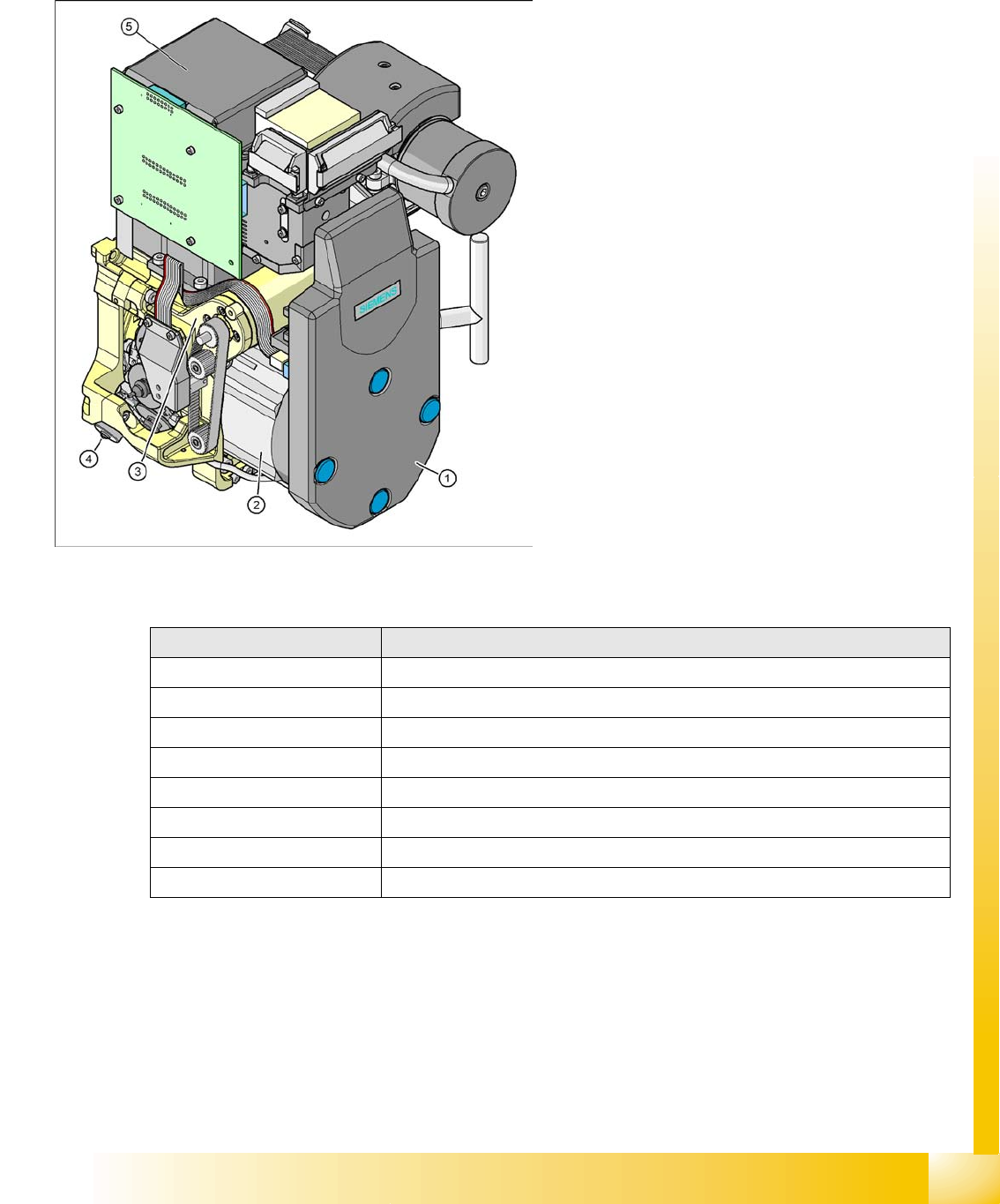
Legend
1. Cover intermediate distributor board, digital
(under the cover)
2. Star drive
3. Z Drive
4. Stepper motor (valve positioning drive)
5. Component camera C&P, type 28 (18x18)
digital or type 29 (27x27) digital, high
resolution component camera 18x18, optional
also for SST29 for 0201 (0.5x0.25 mm) or from
SW 604 also for SST38.
Description 12 segment DLM 3
Component size 1mm x 0,5mm (0402)/0,5mm x 0,25mm (0201) up to 18,7 mm x 18,7 mm
Component height 6,0 mm
Component weight 2,0 g
Placement Accuracy +/- 80 µm for 4 (Sigma)
Angle accuracy +/- 0,7° at 4 (Sigma)
Placement force 2,4 - 5,0 N
Nozzle types 901, 904, 905; 911-919; 920-925; 931-937
Nozzle Changer set up for each magazine or set up for each garage
Technical Data - C&P12
C&P6/12 Placement Head
Overview Camera Modularity at the C&P12 Head
Student Guide Advanced Level 2 SIPLACE D Series
C&P6/12 Placement Head EN 05/2007
8-2
8.1.2 Camera Modularity at the C&P12 Head
For further values, refer to the official camera description.
8.1.3 Overview of C&P6/12 Head Parts
NOTE:
The standard camera on the C&P12 is the 28.sst, although the component camera 29.sst, with
a higher resolution (for small 0201 components), can be installed as an option (the same
maximum component dimensions apply in this case).
Smaller maximum component dimensions apply when using the SST38 camera option.
For further settings and data for the C&P12 head, see the specifications for the relevant option.
Description 12 segment standard SST29 12 segment with SST38
Component size: Flip Chip/Bare
Die
0.6 mm x 0.3 mm (0201) 0.2 mm x 0.1 mm (01005) placement
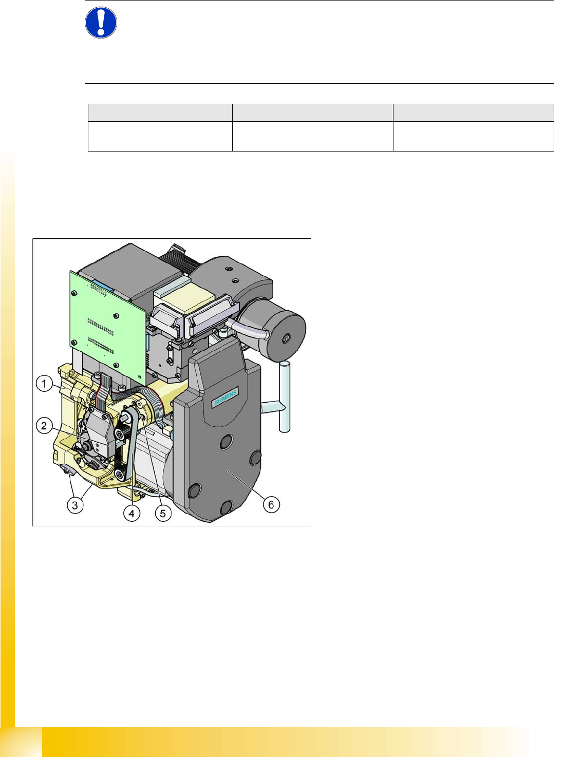
8-1: C&P12 head
Legend - overview of parts 1
1. Collect&Place head 12 (DLM3)
[03041228-xx] (shown)
Collect&Place head 6 (DLM3)
[03048341-xx] (not for D4)
2. Light barrier "Z Axis Up " (behind the cover)
[00347297-xx]
3. Valve positioning drive, placement circuit
[00368076-xx]
Valve positioning drive, reject circuit
[00368074-xx]
4. Z-axis toothed belt
[00334936-xx]
5. Z-axis drive / DLM2
[03038908-xx]
6. Intermediate distributor, digital (behind the
cover)
[00330648-xx]
C&P6/12 Placement Head
Training Note Overview
Student Guide Advanced Level 2 SIPLACE D Series
EN 05/2007 C&P6/12 Placement Head
8-3
8.1.4 Training Note
You know the C&P placement head from your work or from the AL1 course, so that explanations and
illustrations would only be a repetition here.
In this advanced course, we will be covering in detail the programming options and their influence on the
placement head procedure.
If any questions arise or you do not understand anything, please clarify this at once. You will not benefit
from waiting until the end of the course.
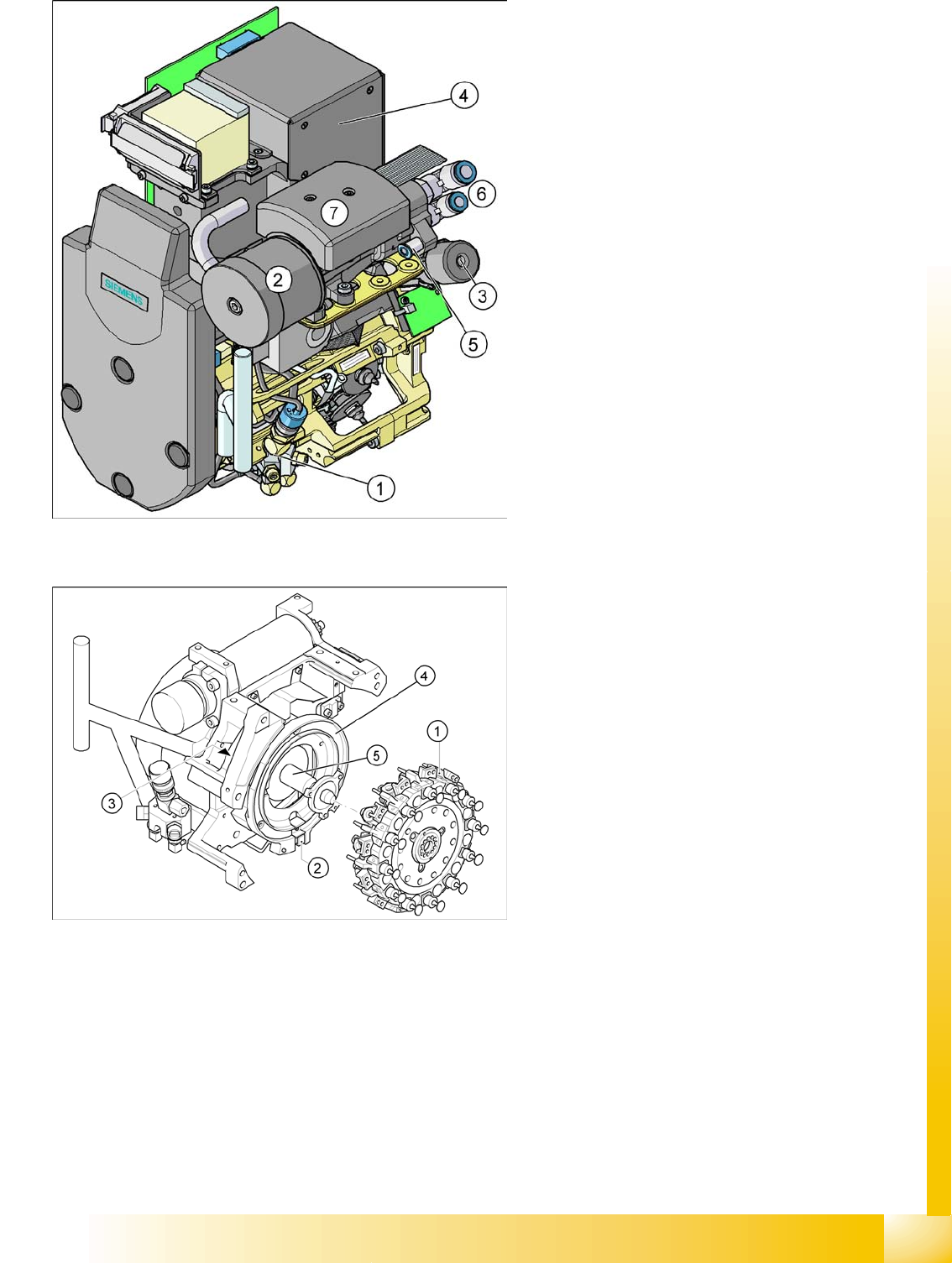
8-2: C&P12 head
Legend - overview of parts 2
1. Forced air unit with electromagnetic valve
(version 02 – downwards compatibility)
[00367793-xx]
2. Silencer
[03003134-xx]
3. Turning station / DLM2
[00341780-xx]
4. Component camera 18x18
[03014449-xx]
Component camera 27 x 27
[03018637-xx]
5. Compressed air supply for forced air unit
6. Compressed air supply for vacuum generator
(holding circuit and pick/place)
7. Vacuum measurement board (under the
cover)
8-3: C&P12 head
Legend - overview of parts 3
1. Star fitted / DLM2
2. "Z-axis down" sensor
3. RSF digital encoder 12/DLM2
4. Circular guide (raceway), aligned to star drive
axis
5. Star drive axis, centered by head housing and
Z-axis claw