D-serie LEVEL II.pdf - 第103页
Gantry Checking the DIP Sw itch Settings S tude nt Guide Advanced Level 2 SIPLACE D Series EN 05/2007 Gantry 6-17 6.3.4 Checking the DIP Switch 6.3.4.1 D IP Switch on V ision Board * You may find that not all gantries ar…
Gantry
Settings Description of Boards at Gantry
Student Guide Advanced Level 2 SIPLACE D Series
Gantry EN 05/2007
6-16
6.3.3.2 Vision Processor Board (Digital)
The Vision processor board is mounted on the gantry head distributor board. This PCB is used for all
four gantries.
See also:
J DIP Switch on Vision Board [J6-17]
6.3.3.3 CAN 16 Bit Processor Board (TQ Module)
Description of 7-segment display (normal operation "." flashes):
After switch ON the machine appears " 0 " on the display
Display "b" --> BIOS was started.
Display flashes alternatively between "b" and "." --> no application available or unable to start
application.
Display " -I " and " I- " application was loaded.
"." flashes on the display --> ready for operation.
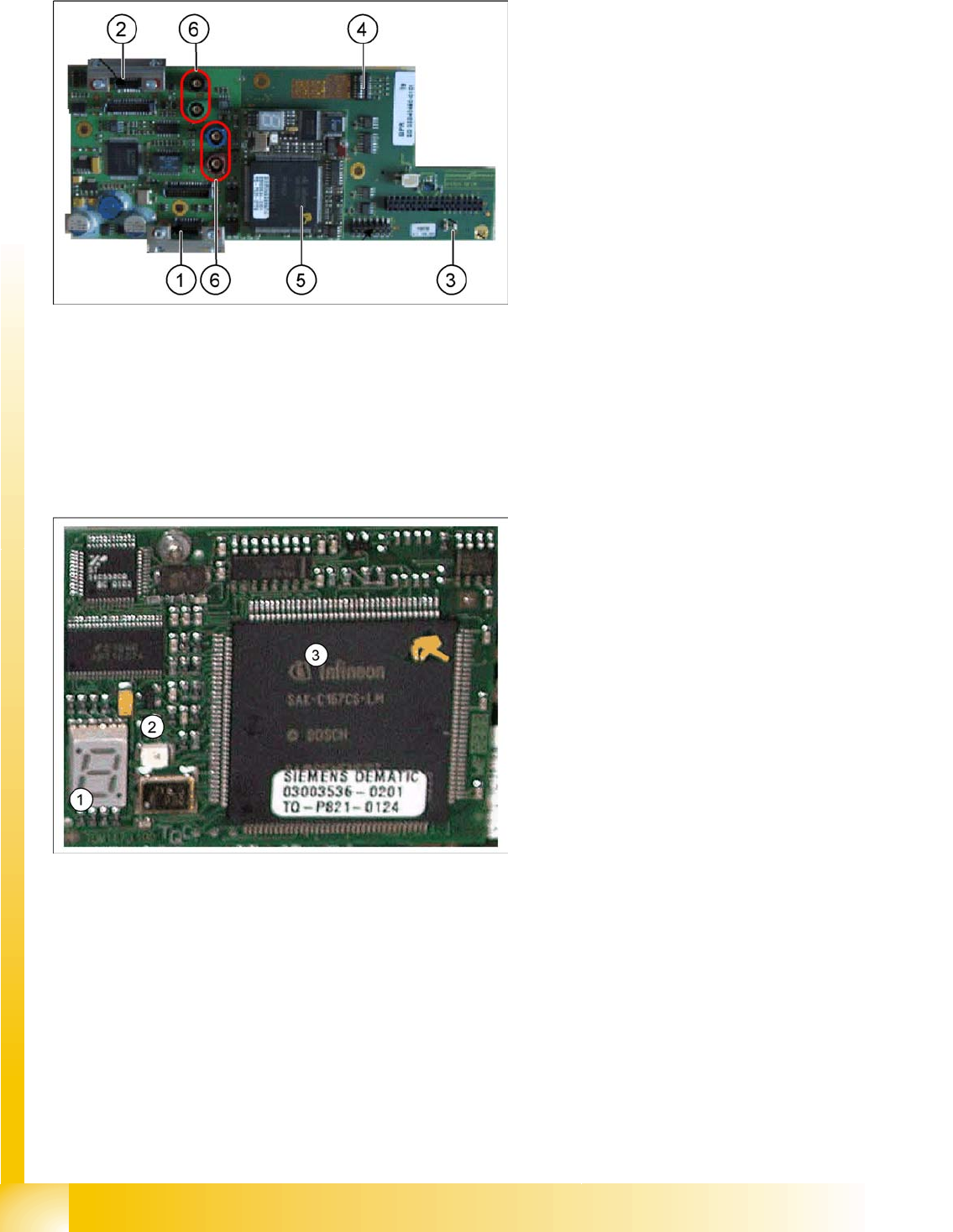
6-10: Vision processor board
Legend
1. X8 Connector illumination and video signals
PCB camera
2. X3 Connector illumination and video signals
component camera
3. LED‘s P15V - 15Volt / Vcc - Power supply
Vision board
4. DIP switch
5. CAN Processor 16 Bit (TQM Module)
6. Connector X22 - X24 Connectors for the video
cable to the trailing cable
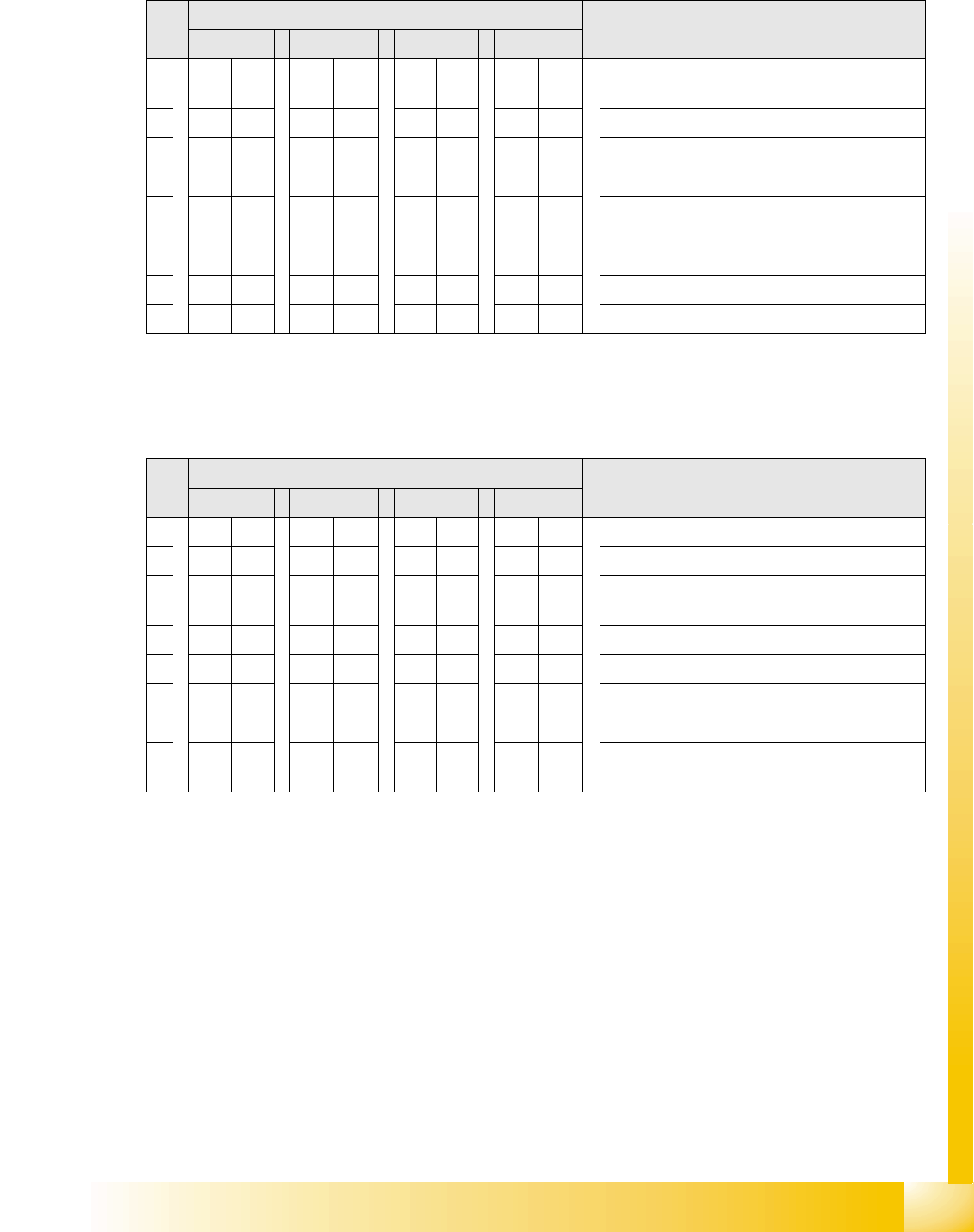
6-11: 16 bit processor (TQ module)
Legend
1. 7 Segment display
2. LED for manual RESET of processor
3. 16 Bit Processor
The 16 BIT CAN processor is used for various
different functions in the following units:
(see chapter Communication and Control as well)
Vision board, communication and control via
the CAN Bus to the vision computer.
Gantry head distributor, control of head
processes and vacuum
Gantry
Checking the DIP Switch Settings
Student Guide Advanced Level 2 SIPLACE D Series
EN 05/2007 Gantry
6-17
6.3.4 Checking the DIP Switch
6.3.4.1 DIP Switch on Vision Board
* You may find that not all gantries are available - this depends on the machine type.
6.3.4.2 DIP Switch on Gantry Head Distributor
* You may find that not all gantries are available - this depends on the machine type.
S Setting for gantry* Note
1 2 3 4
1 OFF OFF OFF OFF Boot mode – 16 bit CAN processor via
connector X11
2 OFF OFF OFF OFF Reset – 16 bit CAN processor on subboard
3 OFF ON OFF ON P0 - address switch 1 --> gantry
4OFF OFF ON ONP1 - address switch 2 --> gantry
5 OFF OFF OFF OFF WPE - write protect enable, currently
deactivated
6 OFF OFF OFF OFF CAN R - switch terminating resistor CAN bus
7ONONONONTest 1 - CAN 1 MBit/s --> ON
8ONONONONTest 0 - CAN IDs --> ON
S Setting for gantry* Note
1 2 3 4
1 OFF ON OFF ON P0 - gantry ID0 address switch 1 --> gantry
2OFF OFF ON ONP1 - gantry ID1 address switch 2 --> gantry)
3 OFF OFF OFF OFF S1 – switch for DLM head (delay switching on
LB down – Z-axis)
4 OFF OFF OFF OFF BL – activates boot loader for the serial port
5 OFF OFF OFF OFF Reset – CAN processor, 16 bit (TQM module)
6 OFF OFF OFF OFF C0 – currently no function
7 OFF OFF OFF OFF C1 – currently no function
8 OFF OFF OFF OFF S2 – switch for DLM head (currently no
function)

Gantry
Settings Mechanical Settings for Incremental Encoder
Student Guide Advanced Level 2 SIPLACE D Series
Gantry EN 05/2007
6-18
6.3.5 Mechanical Settings for Incremental Encoder
The incremental encoders (read units) on the X and Y axes are set exactly to the position of the
incremental scale. The two limit marks on the incremental encoder show the top/bottom position of the
scale. They are also mechanically set to a distance of 0.4 mm +/-0.1 mm to the incremental scale.
After setting the incremental encoder, you need to check the zero pulse and the track signals.
If the installation was performed correctly, this generally means that the counting and zero pulses will be
accurate. For error analysis and solution, check these signals with the oscilloscope. (See service
manual.)
See also:
J 7.4.1 Track Signals and Zero Pulse [J7-12]
NOTE:
For this setting, use one or more small plastic disks to form a total thickness of 0.4 mm.